Supercharge Your Innovation With Domain-Expert AI Agents!

Compound Spray Minimal Quantity Lubrication Cooling System

A cooling system and micro-lubrication technology, which is applied in metal processing equipment, maintenance and safety accessories, metal processing machinery parts, etc., can solve the problem that the surface quality after processing cannot be guaranteed, it is difficult to form oil film attached to water droplets stably, and lubricating oil cannot be directly applied Reply and other questions

Active Publication Date: 2021-10-29
CONPROFE TECH GRP CO LTD +1
View PDF11 Cites 0 Cited by
  • Summary
  • Abstract
  • Description
  • Claims
  • Application Information

AI Technical Summary

Problems solved by technology

[0004] However, the existing low-temperature water mist oil mist cooling and lubrication system usually transports water and oil mist to the nozzle separately, and then mixes and atomizes the water and oil mist again at the nozzle through compressed gas. The particles formed by this atomization method It is relatively random and may form three types of particles: water particles, oil particles and water droplets attached to the oil film. Due to the immiscibility of oil and water, if the water particles first adhere to the surface of the workpiece and the tool, the lubricating oil cannot be directly coated On the surface of the tool and the workpiece, the lubrication effect cannot be produced, and thus a stable and good surface roughness cannot be guaranteed
[0005] Patent document CN 206748079U discloses a low-temperature water mist oil mist cutting cooling and lubrication supply system. In this technical solution, a composite spray is formed through a vortex atomizing nozzle. As a result, the formation of composite spray particles is random, it is difficult to stably form oil film with water droplet particles, and the stable surface quality after processing cannot be guaranteed.

Method used


Image

  • Compound Spray Minimal Quantity Lubrication Cooling System
  • Compound Spray Minimal Quantity Lubrication Cooling System

Examples


Embodiment Construction

[0020] This part will describe the specific embodiment of the present invention in detail, and the preferred embodiment of the present invention is shown in the accompanying drawings. Each technical feature and overall technical solution of the invention, but it should not be understood as a limitation on the protection scope of the present invention.

[0021] In the description of the present invention, it should be understood that the orientation descriptions, such as up, down, front, back, left, right, etc. indicated orientations or positional relationships are based on the orientations or positional relationships shown in the drawings, and are only In order to facilitate the description of the present invention and simplify the description, it does not indicate or imply that the device or element referred to must have a specific orientation, be constructed and operated in a specific orientation, and thus should not be construed as limiting the present invention.

[0022] I...


PUM


Abstract

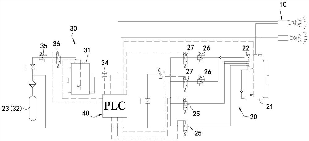
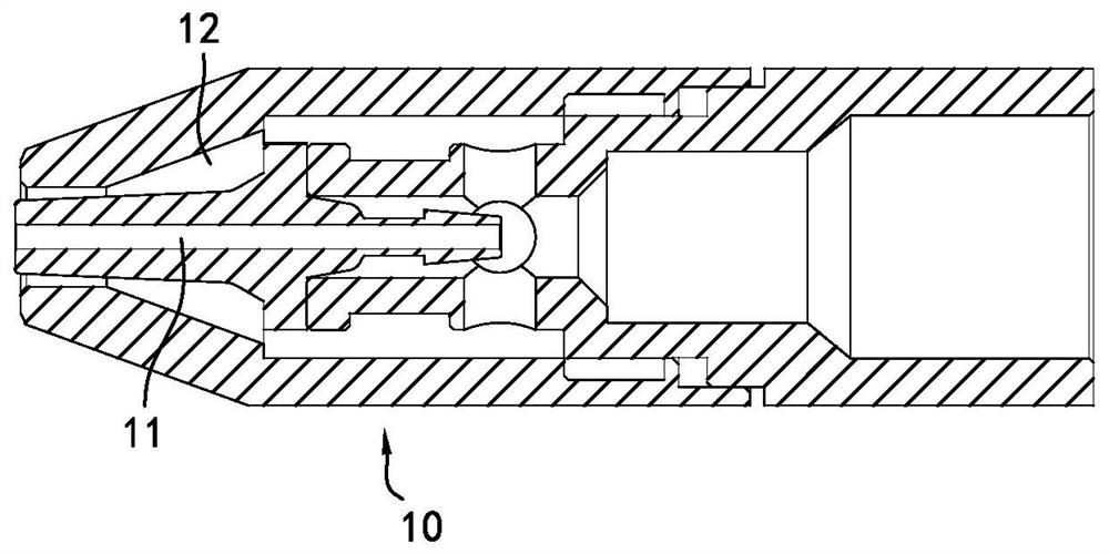
The invention discloses a composite spray micro-lubrication cooling system, which includes a nozzle, an inner spray chamber and an outer spray chamber arranged concentrically inside and outside; a water supply device connected with the inner spray chamber for providing pressure and flow Adjustable water; and an oil mist supply device, connected with the external injection chamber, for providing oil mist with adjustable pressure and flow rate, adopting a concentric nozzle structure to make water and oil mist mix according to a predetermined ratio, and using oil to Due to the characteristics of the surface floating on water, the oil mist airflow output by the outer ring will break up the water to form a spray of oil film with water droplets attached, so as to ensure that the oil film is coated on the workpiece and tool to increase the evaporative cooling effect and take it away more quickly heat generated during processing.

Description

technical field [0001] The invention relates to the technical field of cooling systems, in particular to a compound spray micro-lubrication cooling system. Background technique [0002] Minimal quantity lubrication cooling cutting usually refers to the mixing and vaporization of compressed gas and a small amount of lubricating oil to form a micron-sized droplet oil mist, which is sprayed into the cutting area through the nozzle at high speed, so as to effectively cool and lubricate the cutting area. The existing common minimum quantity lubrication cooling system sprays oil mist to the cutting area, and the heat generated by the cutting process is limited by air cooling, that is, if the heat generated by cutting cannot be effectively removed, the oil film will quickly fail and the lubrication effect For this reason, the prior art also uses compressed gas such as liquid nitrogen that can quickly vaporize and absorb heat under normal temperature and pressure, and then quickly t...

Claims


Application Information

Patent Timeline
Patent Type & Authority Patents(China)
IPC IPC(8): B23Q11/10
CPCB23Q11/1038B23Q11/1046B23Q11/1076
Inventor 颜炳姜李伟秋王勇
Owner CONPROFE TECH GRP CO LTD
Features
  • R&D
  • Intellectual Property
  • Life Sciences
  • Materials
  • Tech Scout
  • Unparalleled Data Quality
  • Higher Quality Content
  • 60% Fewer Hallucinations
Learn More