
Calibration-target-free universal hand-eye calibration method based on 3D vision

A technology of hand-eye calibration and calibration board, which is applied in the direction of manipulators, program-controlled manipulators, manufacturing tools, etc., which can solve the problems of inconvenient, inability to achieve online calibration, and inability to carry calibration boards

Inactive Publication Date: 2019-11-15
SHANGHAI RO INTELLIGENT SYST
View PDF4 Cites 15 Cited by
  • Summary
  • Abstract
  • Description
  • Claims
  • Application Information

AI Technical Summary

Problems solved by technology

This hand-eye calibration method has the following three disadvantages: first, the nonlinear optimization problem makes solving the above equations more complicated and time-consuming, and cannot achieve online calibration; second, the process of determining the attitude of the calibration board will introduce large errors, As a result, the accuracy of the final hand-eye calibration is not high; third, it is inconvenient or even impossible to use an accurate calibration plate in some occasions, for example, the mobile robot arm cannot carry the calibration plate due to its limited load

Method used


Image

  • Calibration-target-free universal hand-eye calibration method based on 3D vision
  • Calibration-target-free universal hand-eye calibration method based on 3D vision
  • Calibration-target-free universal hand-eye calibration method based on 3D vision

Examples


Embodiment 1

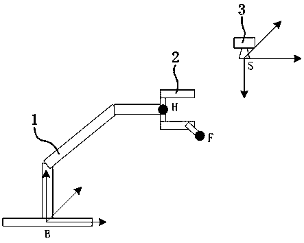
[0060] Example 1 - Eye-to-hand:

[0061] See figure 1 , in this implementation, the table tennis ball is clamped by the end effector of the robotic arm. The center of the table tennis ball is taken as the feature point F. There are at least two ways to extract the center position of the table tennis ball: first, use the depth image data of the 3D camera to perform Hough transform; second, segment the yellow circular area from the 2D image data, which is the closest to the camera Adding a radius of the ping-pong ball to the point along the camera depth direction is the center of the ball.

[0062] The specific steps of the general hand-eye calibration method based on 3D vision are as follows, including,

[0063] Step S1, keep the position of the center of the flange of the end effector of the mechanical arm unchanged, and control the end effector to only perform rotational movement. As far as the controller level of the manipulator is concerned, only the ABC Euler angles re...

Embodiment 2

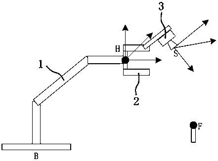
[0104] Example 2 - Eye-in-hand:

[0105] See figure 2 , the operation steps of the eye-in-hand calibration technique are basically the same as the above-mentioned embodiment, except that in step S2, the attitude of the recording robot arm is added, and the specific implementation methods are not described here one by one.


PUM


Abstract

The invention discloses a calibration-target-free universal hand-eye calibration method based on 3D vision. The calibration-target-free universal hand-eye calibration method based on 3D vision is common for the eye-to-hand condition and the eye-in-hand condition. The calibration-target-free universal hand-eye calibration method based on 3D vision comprises the steps that firstly, the center position of a flange plate of an end executor of a mechanical arm is kept constant, the end executor is controlled to only rotate, and a 3D vision sensor is utilized to collect coordinates of at least fourfeature points F for sphere center fitting; then, the posture of the end executor of the mechanical arm is kept constant, the end executor is controlled to only conduct horizontal movement, the coordinates of at least three feature points F are collected by a 3D camera, and a controller of a robot is used for recording or calculating the corresponding center position of the flange plate so as to estimate the rigid transformation parameter. The calibration-target-free universal hand-eye calibration method based on 3D vision has the beneficial effects that space information of the 3D vision sensor are fully utilized, a high error generated when the posture of the calibration target is measured is avoided, it is not needed to solve a complicated high-dimensional nonlinear matrix equation, andtherefore the calibration precision and calibration efficiency are high.

Description

technical field [0001] The invention relates to the field of industrial robots and automation, in particular, a general hand-eye calibration method based on 3D vision without a calibration board. Background technique [0002] In the automation system of the industrial manipulator, how to correctly obtain and understand the information about the operating space is a very critical issue. In most robotic arm systems, the best way to perceive the environment is to use visual data, because visual data can be obtained in a contactless and safe manner. The prerequisite for analysis in machine vision is hand-eye calibration. The so-called hand-eye calibration is to measure the relative posture and position relationship between the camera and the manipulator, which is a basic problem in manipulators. What the robotic arm system needs to analyze is a three-dimensional world, and 3D visual data can best be used to describe a 3D scene. In addition, the cost of 3D visual sensors has be...

Claims


Application Information

Patent Timeline
Patent Type & Authority Applications(China)
IPC IPC(8): B25J9/16
CPCB25J9/1692
Inventor 高小嵩覃江华
Owner SHANGHAI RO INTELLIGENT SYST
Learn More