Energy storage charging pile

A charging pile and energy storage technology, applied in charging stations, vehicle energy storage, electric vehicle charging technology, etc., can solve problems such as inability to use directly in parallel and large differences in battery packs

Pending Publication Date: 2019-11-15
SHENZHEN YINGFEIYUAN TECH CO LTD
View PDF0 Cites 2 Cited by
  • Summary
  • Abstract
  • Description
  • Claims
  • Application Information

AI Technical Summary

Problems solved by technology

[0005] What's more prominent is that when retired batteries are used as energy storage, different battery packs have greater differences and cannot be directly used in parallel, and the charging and discharging process needs to be treated differently

Method used


Image

  • Energy storage charging pile
  • Energy storage charging pile
  • Energy storage charging pile

Examples


Embodiment approach 1

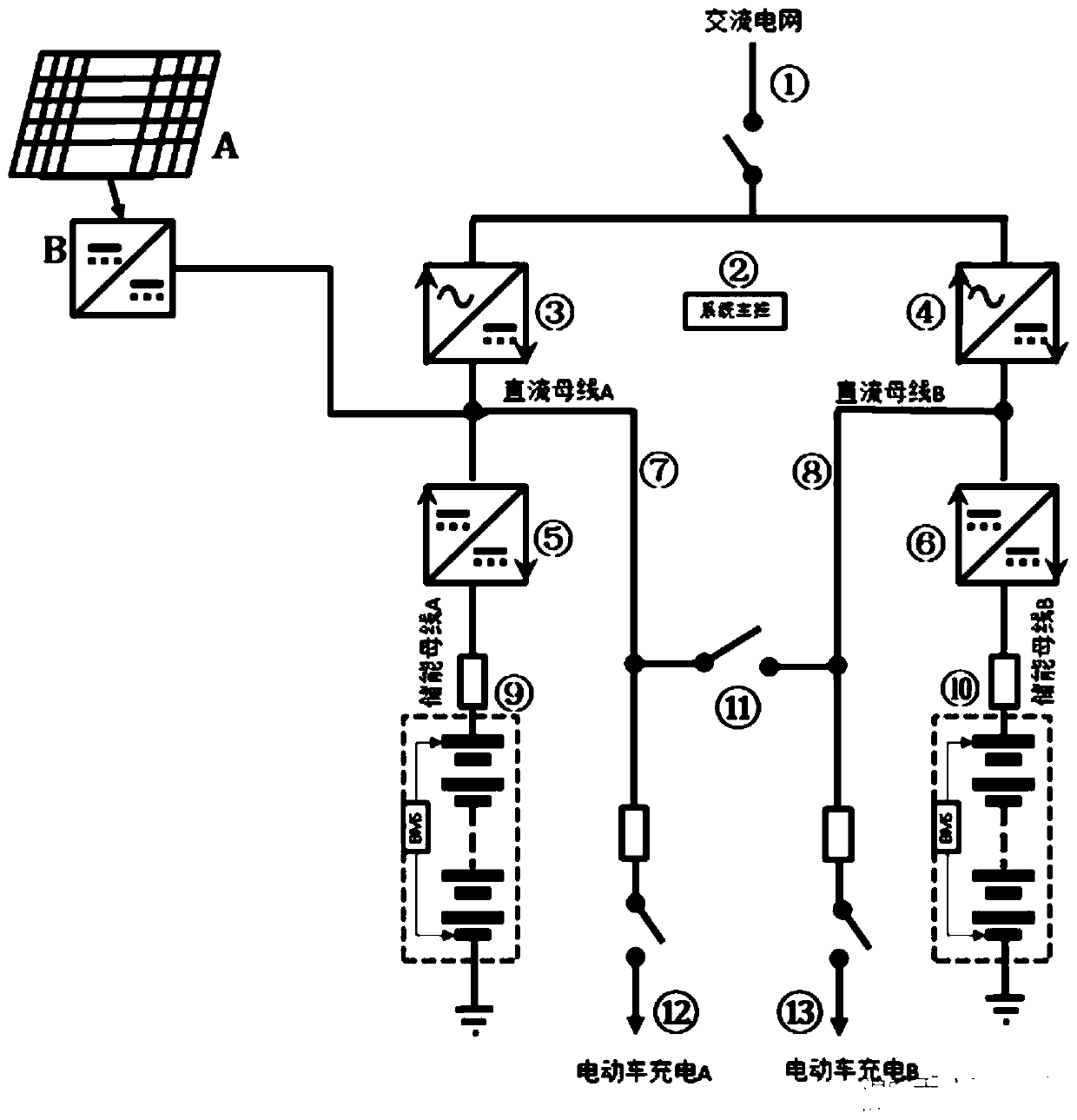
[0039] Such as figure 2 , the photovoltaic array A is connected to the DC bus through the MPPT maximum power tracking conversion device B,

[0040] The above embodiment is a photovoltaic energy storage charging system. The electric energy can be supplemented by the photovoltaic array, and the DC bus is powered through the maximum power tracking, and the electric vehicle is powered through the bus, and the excess electric energy is stored in the energy storage device. When there is no solar energy or the solar energy is not enough, the alternating current or energy storage device is used to discharge to provide electric energy to the DC bus.

[0041] Such as image 3 As shown, the first DC / DC conversion device 5 and the second C / DC conversion device 6 including high-frequency isolation conversion, as well as the first DC bus 7 and the second DC bus 8; the first connection point of the DC / DC conversion device Connected to the first DC bus 7 and the second DC bus 8; the second...

Embodiment approach 2

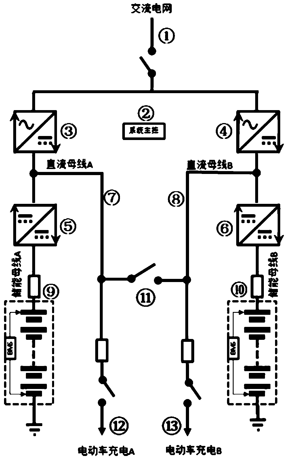
[0049] Such as Figure 4 , the photovoltaic array A is connected to the DC bus through the MPPT maximum power tracking conversion device B,

[0050] The above embodiment is a photovoltaic energy storage charging system. The electric energy can be supplemented by the photovoltaic array, and the DC bus is powered through the maximum power tracking, and the electric vehicle is powered through the bus, and the excess electric energy is stored in the energy storage device. When there is no solar energy or the solar energy is not enough, the alternating current or energy storage device is used to discharge to provide electric energy to the DC bus.


PUM


Abstract

The invention discloses an energy storage charging pile. The energy storage charging pile comprises high-frequency isolation DC / DC conversion devices and direct current buses, high-frequency isolationAC / DC conversion devices and direct current buses, an electric vehicle charging device and a charging port as well as energy storage devices and energy storage buses, wherein the DC / DC conversion devices can be unidirectional or bidirectional; and the AC / DC conversion devices can also be unidirectional or bidirectional. The different energy storage devices can be treated differently, and can be respectively charged or discharged, meanwhile, electric energy of an alternating-current power grid, electric energy stored by the energy storage devices and electric energy of a battery in an electricvehicle can be combined simultaneously, so that the electric energy of the alternating-current power grid, the electric energy stored by the energy storage devices and the electric energy of the battery in the electric vehicle can flow freely, impact of charging on the alternating-current power grid can be reduced, and meanwhile, the battery in the vehicle can be effectively utilized as an energystorage device to feed the power grid reversely or charge the energy storage devices, and thus, an integrated solution is achieved.

Description

technical field [0001] The invention relates to an electric vehicle charging pile, in particular to an energy storage charging pile. . Background technique [0002] Generally, electric vehicles get power from the AC grid, but due to the limitation of the AC grid in terms of power supply, especially the limited capacity of a single box-type transformer, it is impossible to connect to a charging pile that exceeds its capacity. At the same time, there may be some differences in the electricity consumption cost of the AC grid in different time periods, and electric vehicle charging is a random electricity consumption, so there may be cases where peak electricity charges are used, or full power charging cannot be performed. If the energy storage device stores electric energy when the electricity bill is low or the grid is idle, and releases the electric energy when the electricity bill is high or the peak of electricity consumption is overloaded, it can greatly alleviate the pro...

Claims


Application Information

Patent Timeline
IPC IPC(8): B60L53/30B60L53/31B60L53/14B60L53/50
CPCB60L53/30B60L53/31B60L53/14B60L53/50Y02T10/72Y02T10/70Y02T90/14Y02T10/7072Y02T90/12
Inventor 王渭渭朱春辉岳兴
Owner SHENZHEN YINGFEIYUAN TECH CO LTD
Why Eureka
Try Eureka