A kind of bouncing flapping wing robot and its bouncing flapping wing method

A robot and rack technology, applied in the field of robotics, can solve problems such as deviation from expectations, large energy consumption, and large landing impact, and achieve the effects of reducing device weight, enhancing bounce stability, and increasing bounce height

Active Publication Date: 2020-11-24
HANGZHOU DIANZI UNIV
View PDF7 Cites 0 Cited by
  • Summary
  • Abstract
  • Description
  • Claims
  • Application Information

AI Technical Summary

Problems solved by technology

[0002] At present, the single jumping robot mainly has difficulties such as high energy consumption, large landing impact and deviation from expectations.

Method used


Image

  • A kind of bouncing flapping wing robot and its bouncing flapping wing method
  • A kind of bouncing flapping wing robot and its bouncing flapping wing method
  • A kind of bouncing flapping wing robot and its bouncing flapping wing method

Examples


Embodiment 1

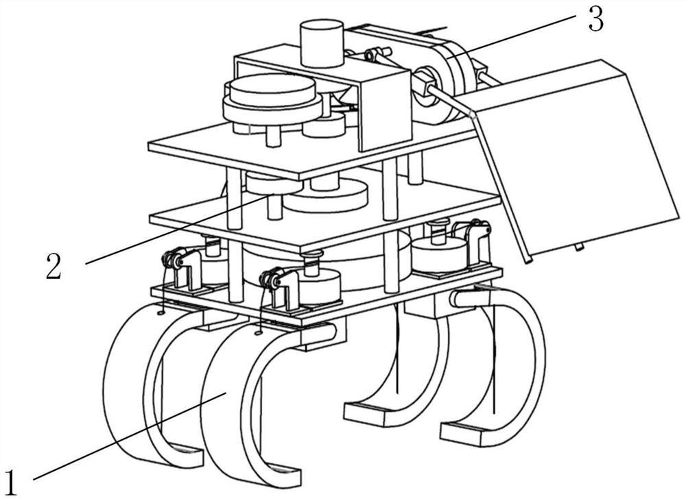
[0039] Such as figure 1 As shown, a bounce flapping wing robot includes a frame, a bounce mechanism 1, a multiplexing drive mechanism 2, a flapping wing mechanism 3, and a control sensor system. The frame includes a bounce base plate 5, a middle base plate 9 and a flapping wing top plate 31 arranged and fixed together in sequence, forming a three-layer gear placement position.

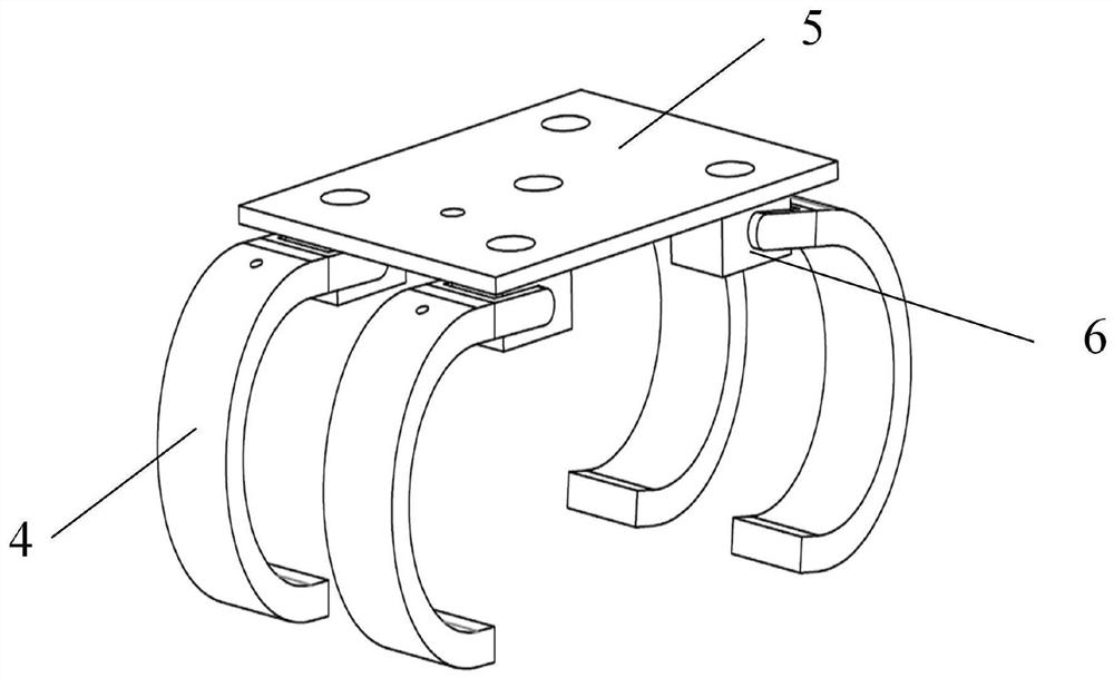
[0040] Such as figure 1 with 2 As shown, the bounce mechanism 1 is installed at the bottom of the entire device, and includes four steering gears 6 and four spring legs 4. The bounce bottom plate 5 is a plate of 250mm×150mm×10mm. Four steering gears 6 are fixed on the four corners of the bottom surface of the bounce base plate 5. The output shaft of the four servos 6. The elastic leg 4 is made of elastic material, specifically rubber. The leg 4 is C-shaped. The inner ends of the elastic legs 4 are provided with rope holes. The inner ends of the four spring legs 4 are fixed to the output shafts of the...

Embodiment 2

[0059] A bouncing flapping wing robot differs from Embodiment 1 in that the material of the switching ring is a permanent magnet, and one of its magnetic poles faces the switching electromagnet.

[0060] In the bouncing flapping method of the bouncing flapping wing robot, the direction of the magnetic pole is changed by switching the forward and reverse energization of the electromagnet, thereby realizing the switching of the switching axis between the upper limit position and the lower limit position. When the switching electromagnet generates repulsive force on the switching ring, the switching shaft is at the lower limit position; when the switching electromagnet generates attraction to the switching ring, the switching shaft is at the upper limit position; embodiment 2 is relative to embodiment 1, the position of the switching shaft is adjusted It is more stable and reliable without relying on gravity.


PUM


Abstract

The invention discloses a bouncing flapping wing robot and a bouncing flapping wing method thereof. Some small insects, such as crickets and grasshoppers, in the natural world, utilize leg muscles tojump and utilize wings to adjust postures in the air, thereby improving stability in the jumping and landing stage. The bouncing flapping wing robot comprises a rack, a bouncing mechanism, a multiplexing driving mechanism and a flapping wing mechanism. The bouncing mechanism comprises four transmission ropes and four bouncing legs. The flapping wing mechanism comprises a flapping wing frame, a flapping wing input shaft, a flapping wing input gear, a first intermediate gear, a second intermediate gear, a third intermediate gear, a flapping wing output gear and a single-side flapping wing assembly. The multiplexing driving mechanism comprises a bouncing transmission assembly, a flapping wing transmission assembly, a power source assembly and a transmission switching assembly. The bouncing flapping wing robot of the invention can drive the bouncing action and the flapping wing action by only using one motor to drive, thereby effectively reducing the weight of the device and being beneficial to improving the bouncing height.

Description

Technical field [0001] The invention belongs to the technical field of robots, and specifically relates to a bounce flapping wing robot and a bounce flapping wing method thereof. Background technique [0002] At present, a single jumping robot mainly has difficulties such as large energy consumption, large landing impact and deviation from expectations. Some small insects in nature, such as crickets, grasshoppers, etc., use leg muscles to take off and use wings to adjust their posture in the air, which enhances the stability of the take-off and landing phases. Therefore, bounce and flapping wing robots have become the focus of research. Summary of the invention [0003] The purpose of the present invention is to provide a bounce flapping wing robot and a method for bounce flapping wings. [0004] The invention is a bouncing flapping wing robot, which includes a frame, a bouncing mechanism, a multiplexing drive mechanism and a flapping wing mechanism. The bounce mechanism includes...

Claims


Application Information

Patent Timeline
Patent Type & Authority Patents(China)
IPC IPC(8): B64C33/02B62D57/02
CPCB62D57/02B64C33/02
Inventor 许明章佳奇陈国金
Owner HANGZHOU DIANZI UNIV
Why Eureka
Try Eureka