Wound tube heat exchanger with baffle plates

A technology of winding tube type and baffle plate, which is applied in the direction of heat exchanger type, heat exchanger shell, indirect heat exchanger, etc. It can improve the uniformity of heat exchange, eliminate the dead zone of flow, and achieve the effect of simple and reasonable structure.

Pending Publication Date: 2019-11-15
ZHONGKAI UNIV OF AGRI & ENG
View PDF0 Cites 4 Cited by
  • Summary
  • Abstract
  • Description
  • Claims
  • Application Information

AI Technical Summary

Problems solved by technology

Due to the traditional wound tube heat exchanger, its spiral wound tube bundle is uninterrupted spiral winding, and diversion pads are set between different pipe networks, it is difficult to install baffles on the shell side, resulting in the fluid flow of the traditional wound tube heat exchanger The heat exchange process is short, and there will be a flow rate stagnation area between adjacent pipes in the same layer of pipe network, especially the area between the gasket and the heat exchange tube will cause a flow dead zone, and it is difficult to further improve the heat exchange efficiency, and the overall heat exchange of the heat exchanger The heat is not uniform, and there is a certain waste of heat exchange capacity. Therefore, it is necessary to overcome and further improve the above shortcomings.

Method used


Image

  • Wound tube heat exchanger with baffle plates
  • Wound tube heat exchanger with baffle plates
  • Wound tube heat exchanger with baffle plates

Examples


no. 1 example

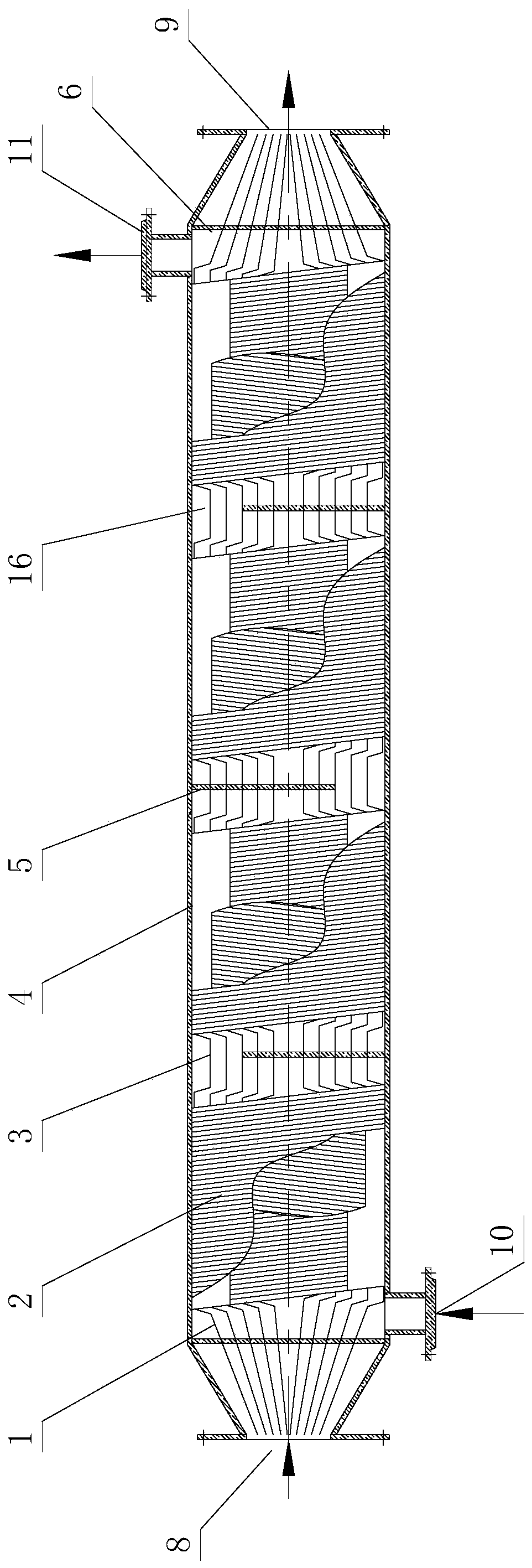
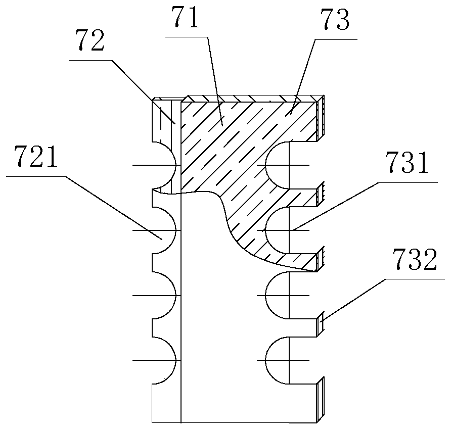
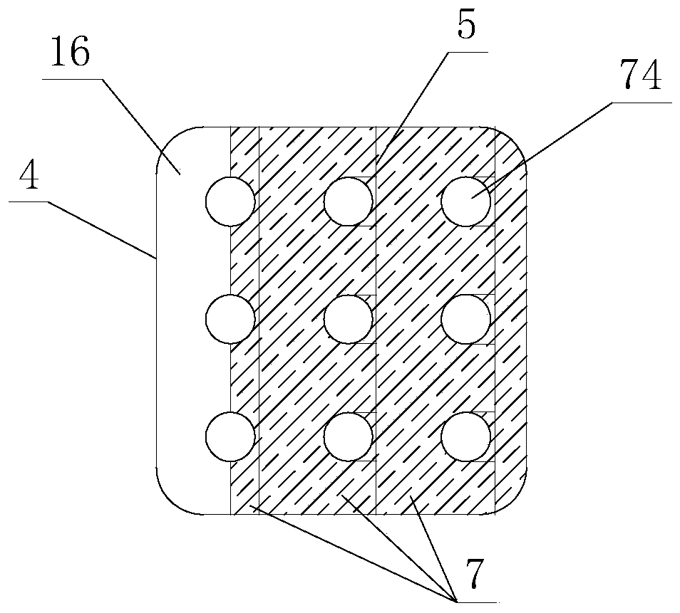
[0024] see Figure 1-Figure 4 , the wound tube heat exchanger with baffles includes a shell 4, and the shell 4 is provided with a plurality of spirally wound heat transfer tubes 1, and the multi-stage spirally wound heat transfer tube 1 is composed of several spirally wound tube segments 2 and several The straight pipe sections 3 are wound alternately; wherein, a plurality of combined baffles 5 are arranged between the straight pipe section 3 and the shell 4, and several combined baffles 5 are arranged vertically along the axis of the shell 4; The two ends of the shell 4 are also provided with tube sheets 6 respectively, and the tube sheets 6 at both ends are separated into a tube side and a shell side heat exchange area.

[0025] The side of the shell 4 is provided with a shell-side inlet 10 and a shell-side outlet 11, and the end is provided with a tube-side inlet 8 and a tube-side outlet 9; the tube-side of the evaporator passes through the evaporation fluid, and the shell-...

no. 2 example

[0041] see Figure 5 , the wound tube heat exchanger with baffles is different from the first embodiment in that: the shell side has multiple processes, and the multi-stage spirally wound heat exchange tubes 1 of different processes are parallel to each other and are not arranged superimposed.

[0042] The shell of this example is two shells. Its multi-section spirally wound heat exchange tube 1 is composed of a spirally wound pipe section 2 and a straight pipe section 3, which are wound in sections. The straight pipe section 3 is arranged between the front and rear spirally wound pipe sections 2, and the tube plates 6 at both ends separate the heat exchanger. Into the tube side and shell side heat exchange area. Two bundles of multi-segment spirally wound heat exchange tubes 1 are arranged in parallel, respectively placed on both sides of the U-shaped shell side, and a shell-side partition 14 is arranged between the two bundles of multi-segment spirally wound heat-exchange t...


PUM


Abstract

The invention discloses a wound tube heat exchanger with baffle plates. The wound tube heat exchanger comprises a shell, wherein a multi-section spiral wound heat exchange tube is arranged in the shell, and the multi-section spiral wound heat exchange tube is formed by winding a plurality of spiral wound tube sections and a plurality of straight tube sections alternately; a plurality of combined baffle plates are respectively arranged between the straight tube sections and the shell and are vertically arranged along the axis of the shell; and the two ends of the shell are further respectivelyprovided with tube sheets, and the shell is divided into a tube-side heat exchange area and a shell-side heat exchange area. By means of the wound tube heat exchanger with the baffle plates, through the improvement of the structure, the baffle plates can be effectively and conveniently installed on the multi-section spiral wound heat exchange tube, so that a dead zone of shell-side flow is effectively eliminated, the disturbance of shell-side fluid is enhanced, the fluid heat exchange process is prolonged, the shell-side heat transfer is finally enhanced, consumables and energy sources are saved, the integral heat exchange uniformity of the heat exchanger is improved, and the practicability is high.

Description

technical field [0001] The invention relates to the field of heat exchangers, in particular to a coiled tube heat exchanger with baffles. Background technique [0002] Winding tube heat exchanger is an important unit equipment in the fields of petrochemical, LNG process, methanol production and fine chemical industry, and it is a relatively efficient heat exchange equipment. Because of the traditional wound tube heat exchanger, the spiral wound tube bundle is uninterrupted spirally wound, and diversion pads are set between different pipe networks, it is difficult to install baffles on the shell side, resulting in the fluid flow of the traditional wound tube heat exchanger The heat exchange process is short, and there will be a flow rate stagnation area between adjacent pipes in the same layer of pipe network, especially the area between the gasket and the heat exchange tube will cause a flow dead zone, and it is difficult to further improve the heat exchange efficiency, and ...

Claims


Application Information

Patent Timeline
Patent Type & Authority Applications(China)
IPC IPC(8): F28D7/02F28F9/24
CPCF28D7/02F28F9/24
Inventor 钟天明陈嘉澍丁力行陈姝夏扬凯刘少达卓献荣李金成
Owner ZHONGKAI UNIV OF AGRI & ENG
Why Eureka
Try Eureka