
Device and method for cleaning external surface of portal heat exchanger

A technology for cleaning devices and heat exchangers, which is applied to cleaning heat transfer devices, flushing, lighting and heating equipment, etc., can solve problems such as hidden safety hazards, increased rental costs, and low operating efficiency, and can reduce the use frequency of cranes, reduce Construction cost and the effect of improving work efficiency

Inactive Publication Date: 2020-09-29
林冠宇
View PDF8 Cites 0 Cited by
  • Summary
  • Abstract
  • Description
  • Claims
  • Application Information

AI Technical Summary

Problems solved by technology

The existing problems are: 1. Manual cleaning has high construction intensity, hidden safety hazards, low operating efficiency, and with the continuous increase of labor costs, the cost of cleaning operations is also increasing; 2. Although foreign cleaning devices use Automatic cleaning, but because the heat exchanger to be washed is constantly rolling, a pair of rotating rollers are required to drive the rolling of the heat exchanger. At the same time, a crane is needed to carry the heat exchanger after washing one.
As the current heat exchanger is getting bigger and bigger, the tonnage of the crane required is getting bigger and bigger, and the daily rental cost is also increasing
In this way, although labor costs are saved, the cost of machinery and tools has risen sharply, which is also an important reason why this foreign technology has not been able to be promoted in China.

Method used


Image

  • Device and method for cleaning external surface of portal heat exchanger
  • Device and method for cleaning external surface of portal heat exchanger
  • Device and method for cleaning external surface of portal heat exchanger

Examples


Embodiment 1

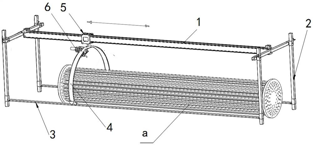
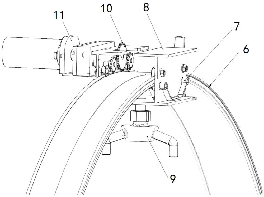
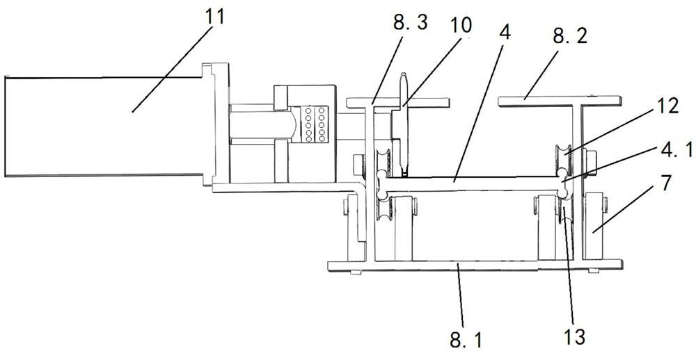
[0023] Embodiment 1, a cleaning device for the outer surface of a portal heat exchanger mentioned in the present invention, including a longitudinal beam 1, a door frame 2, a linear guide rail 3, an arc plate device 4, a longitudinal beam moving mechanism 5, and an arc plate moving device 6 , two or more sets of door frames 2 are added on the outside of the heat exchanger a, a longitudinal beam 1 is installed on the upper part between two or more sets of door frames 2, and two linear guide rails 3 are installed on the lower part , the arc plate device 4 is installed between the longitudinal beam 1 and the linear guide rail 3, and the upper part of the arc plate device 4 is movably connected with the longitudinal beam 1 through the longitudinal beam moving mechanism 5, and the lower part is movably connected with the linear guide rail 3, and the arc plate device 4 is It has a semi-circular structure and is arranged above the heat exchanger a, and the arc plate device 4 is provid...

Embodiment 2

[0033] Embodiment 2, the difference between the present invention and embodiment 1 is:

[0034] Arc plate also can adopt two symmetrical short-arc long arc plates to be hung on the longitudinal beam moving mechanism 5 both sides on the longitudinal beam 1, and the cleaning head at this moment can be two sets of simultaneous cleaning from both sides.


PUM


Abstract

The invention relates to a device for cleaning the outer surface of a portal heat exchanger and a using method thereof. According to the technical scheme, two or more groups of portal frames are additionally arranged on the outer side of the heat exchanger; one end of a longitudinal beam is connected with the middle of the upper portion of one of the two or more groups of portal frames, and the other end of the longitudinal beam is connected with the middle of the upper portion of the other of the two or more groups of portal frames; the two ends of two linear guide rails are respectively connected with the lower portions of the two or more groups of portal frames; an arc plate device is installed between the longitudinal beam and the linear guide rails; the upper portion of the arc platedevice is movably connected with the longitudinal beam through a longitudinal beam moving mechanism, and the lower portion of the arc plate device is movably connected with the linear guide rails; thearc plate device is of a semicircular structure and is arranged above the heat exchanger; a rotary nozzle is arranged on the arc plate device; and the rotary nozzle is driven to do reciprocating motion around the longitudinal beam through the beam moving mechanism, and the heat exchanger is cleaned. The device has the beneficial effects that a cleaning nozzle is used for surrounding and rotatingaround the heat exchanger, and the cleaning nozzle is matched with the rotary nozzle to do reciprocating motion back and forth along the heat exchanger; and meanwhile, due to the adoption of the portal frame type structure, field installation is simple and convenient, the use frequency of a crane on the construction site is reduced, the operation efficiency is improved, and the construction cost is reduced.

Description

technical field [0001] The invention relates to a method for cleaning a heat exchanger cleaning device, in particular to a cleaning device and method for the outer surface of a door type heat exchanger. Background technique [0002] Existing domestic cleaning of the outer surface of the heat exchanger is done by manually holding a high-pressure water gun. The existing foreign technology is that the high-pressure water cleaning gun is fixed on a beam parallel to the heat exchanger to be cleaned, and can be reciprocated. The heat exchanger needs to do 360° rolling to complete the cleaning operation. The existing problems are: 1. Manual cleaning has high construction intensity, hidden safety hazards, low operating efficiency, and with the continuous increase of labor costs, the cost of cleaning operations is also increasing; 2. Although foreign cleaning devices use Automatic cleaning is achieved, but because the heat exchanger to be washed is constantly rolling, a pair of rota...

Claims


Application Information

Patent Timeline
Patent Type & Authority Patents(China)
IPC IPC(8): F28G9/00F28G15/00
CPCF28G9/00F28G15/00
Inventor 林冠宇
Owner 林冠宇
Learn More