Optical imaging lens
An optical imaging lens and lens technology, applied in the lens field, can solve the problems of optical transfer function control to be improved, large optical distortion, imaging deformation, etc., and achieve the effects of good control of optical transfer function, small optical distortion, and short overall system length
- Summary
- Abstract
- Description
- Claims
- Application Information
AI Technical Summary
Problems solved by technology
Method used
Image

Examples
Embodiment 1
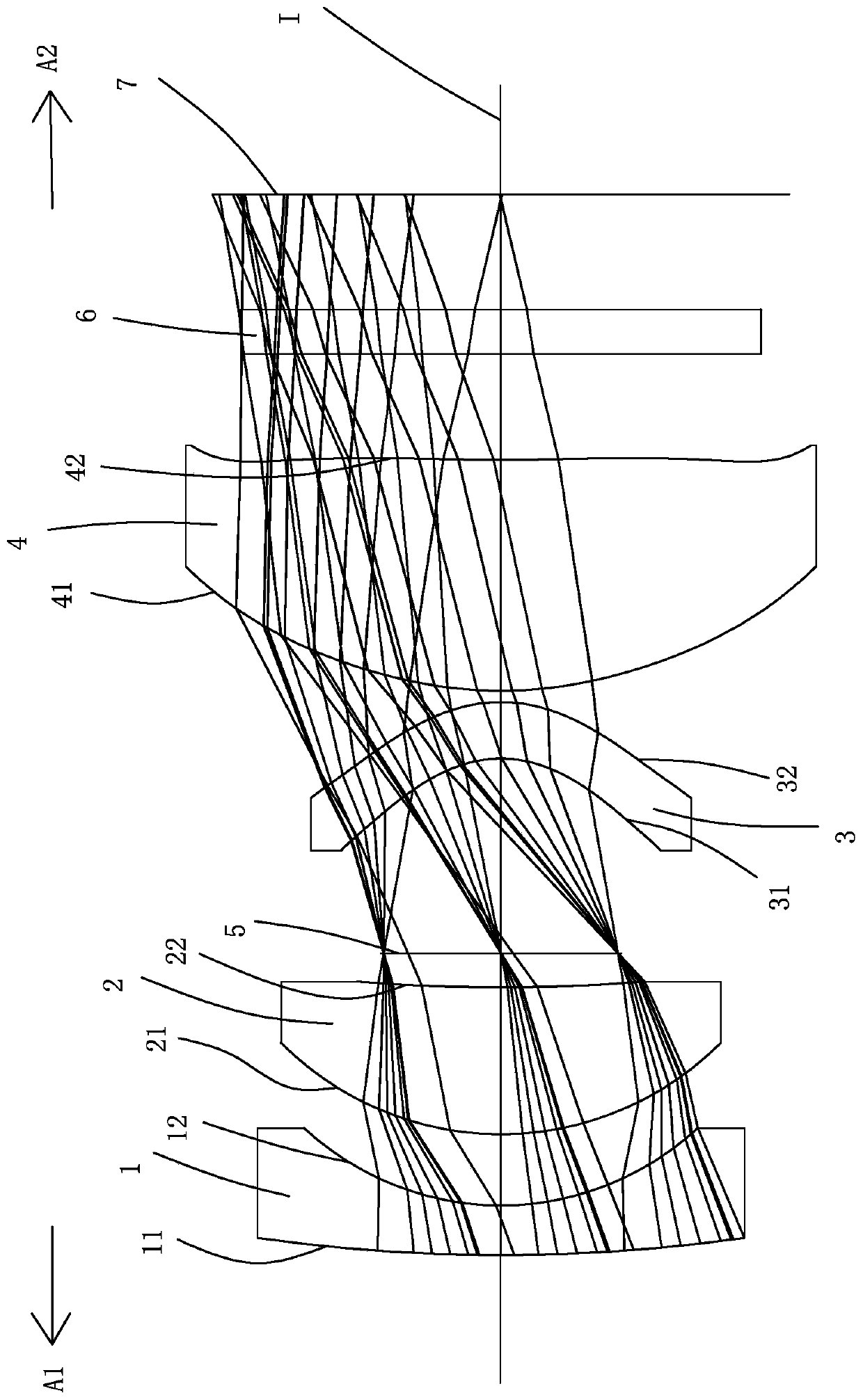
[0061] Such as figure 1 As shown, an optical imaging lens includes a first lens 1, a second lens 2, a diaphragm 5, a third lens 3, a fourth lens 4, and a protective glass along an optical axis I from the object side A1 to the image side A2. 6 and an imaging surface 7; the first lens 1 to the fourth lens 4 each include an object side facing the object side A1 and allowing the imaging light to pass through and an image side facing the image side A2 and allowing the imaging light to pass through;
[0062] The first lens 1 has negative refractive power, the object side 11 of the first lens 1 is convex, and the image side 12 of the first lens 1 is concave.
[0063] The second lens 2 has positive refractive power, the object side 21 of the second lens 2 is convex, and the image side 22 of the second lens 2 is concave.
[0064] The third lens 3 has a negative refractive power, the object side 31 of the third lens 3 is concave, the image side 32 of the third lens 3 is convex, the obj...
Embodiment 2
[0089] Such as Figure 7 As shown, the concave-convex surface and refractive index of each lens in this embodiment are the same as those in the first embodiment, only the optical parameters of the curvature radius of each lens surface, lens thickness, lens aspheric coefficient and system focal length are different.
[0090] The detailed optical data of this specific embodiment are shown in Table 2-1.
[0091] Detailed optical data of Table 2-1 Example 2
[0092] surface Diameter (mm) Radius of curvature (mm) Thickness (mm) material Refractive index Dispersion coefficient focal length(mm) - subject surface 768.421 Infinity 650.000 11 first lens 5.025 12.363 0.470 H-QK3L 1.487 70.420 -8.770 12 4.127 3.102 0.783 21 second lens 3.785 3.166 1.261 H-ZLAF75A 1.904 31.318 4.332 22 3.105 15.411 0.466 5 aperture 2.328 Infinity 2.015 31 third lens 3.067 -1.0...
Embodiment 3
[0099] Such as Figure 13 As shown, the surface concave-convex and the refractive power of each lens in this embodiment are approximately the same as those in Embodiment 1, only the image side of the fourth lens 4 is a convex surface, and the radius of curvature, lens thickness, and lens aspheric coefficient of each lens surface are in addition And the optical parameters of the focal length of the system are also different.
[0100] The detailed optical data of this specific embodiment are shown in Table 3-1.
[0101] Detailed optical data of the third embodiment of table 3-1
[0102]
[0103]
[0104] Please refer to the following table for the detailed data of the parameters of each aspheric surface in this specific embodiment:
[0105] surface 31 32 41 42 K= -2.2086E+00 -1.5512E+00 -1.3984E+01 9.4235E+01 a 4 =
-8.3301E-02 -7.2285E-03 -6.4244E-05 -8.6349E-03 a 6 =
1.3222E-03 -9.4361E-03 2.0053E-04 1.0059E-03 a 8 =
3.50...
PUM
 Abstract
Description
Claims
Application Information
 - R&D
- Intellectual Property
- Life Sciences
- Materials
- Tech Scout
- Unparalleled Data Quality
- Higher Quality Content
- 60% Fewer Hallucinations
Browse by: Latest US Patents, China's latest patents, Technical Efficacy Thesaurus, Application Domain, Technology Topic, Popular Technical Reports.
© 2025 PatSnap. All rights reserved.Legal|Privacy policy|Modern Slavery Act Transparency Statement|Sitemap|About US| Contact US: help@patsnap.com