Simulation method for motion control of changeable rotating center of dynamic positioning ship

A technology of rotation center and simulation method, which is applied in general control systems, control/regulation systems, instruments, etc., can solve the problems of not being able to find technical documents, and achieve the effect of reducing simulation errors

Active Publication Date: 2019-11-15
HARBIN ENG UNIV
View PDF15 Cites 0 Cited by
  • Summary
  • Abstract
  • Description
  • Claims
  • Application Information

AI Technical Summary

Problems solved by technology

[0004] At present, there are few researches in this area at home and abroad. Although Kongsberg has a complete dynamic positioning system product, due to the confidentiality of the technology, no relevant technical literature can be found.

Method used


Image

  • Simulation method for motion control of changeable rotating center of dynamic positioning ship
  • Simulation method for motion control of changeable rotating center of dynamic positioning ship
  • Simulation method for motion control of changeable rotating center of dynamic positioning ship

Examples


Embodiment 1

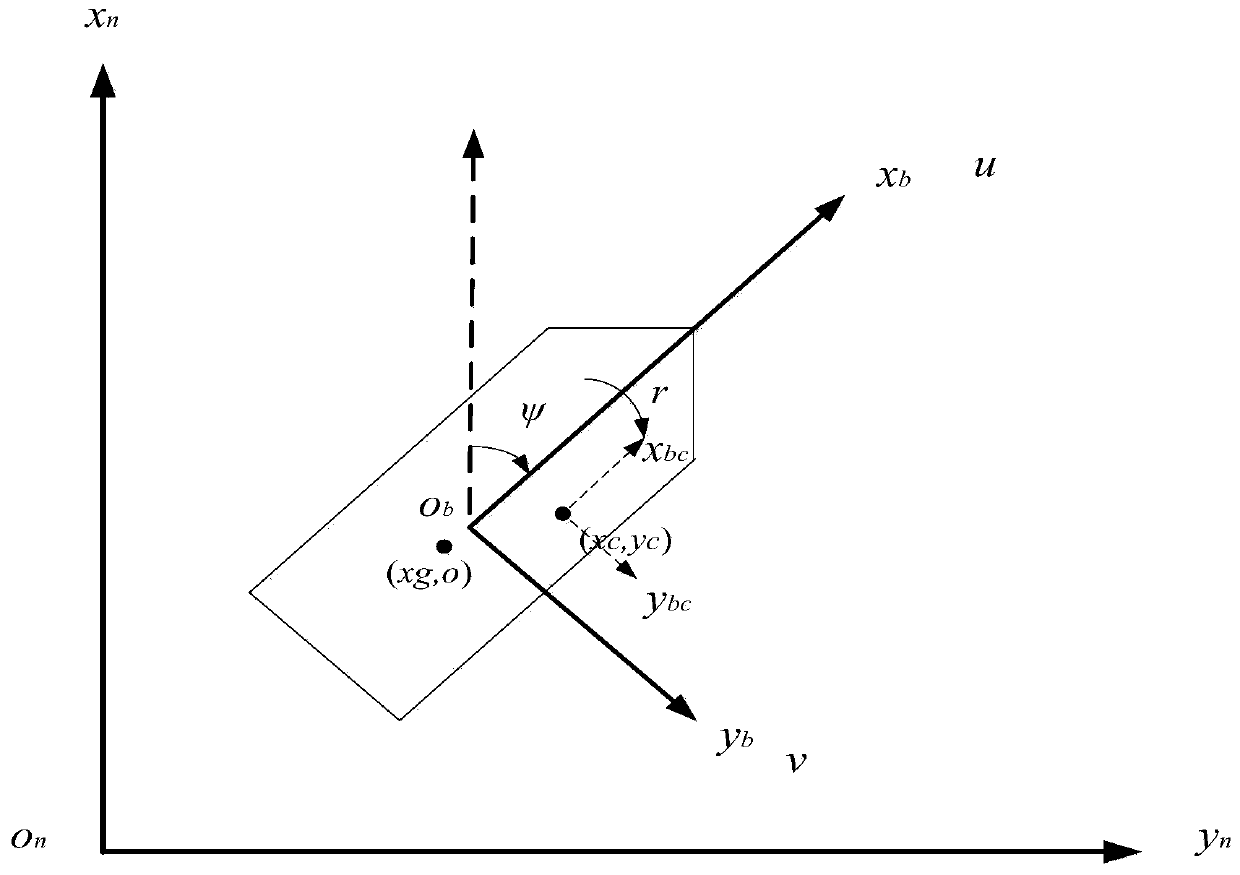
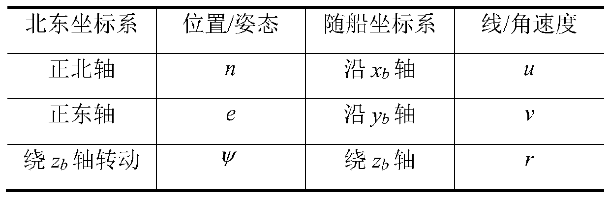
[0052] The invention aims at the motion control of the variable rotation center of the dynamic positioning ship, establishes a three-degree-of-freedom motion mathematical model of the variable rotation center of the ship, proposes a thrust sub-optimized mathematical model of the variable rotation center, and constructs a variable rotation center Dynamic positioning simulation system with central control function. The mathematical model of the ship's variable rotation center motion includes motion equations and dynamic equations. The kinematic equation of the variable rotation center is derived from the conventional three-degree-of-freedom motion equation of the ship according to the relationship between the position of the rotation center and the ship center. The dynamics equation of the ship's variable rotation center, the idea adopted in this patent is based on the composition characteristics of the ship's dynamics equation, the rigid body dynamics equation of the ship's var...

Embodiment 2

[0118] The motion control simulation steps of the dynamic positioning ship variable rotation center are as follows:

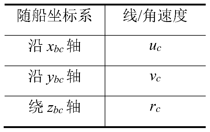
[0119] The first step is to set the rotation center point of the ship in the rotation center setting module according to the task requirements and the corresponding operation mode. The position of the rotation center point in the hull coordinate system is (x c ,y c ) are respectively transmitted to the three-degree-of-freedom motion mathematics module, the thrust distribution module and the motion state conversion module of the variable rotation center.

[0120] The second step is to determine the speed of the center of rotation of the ship and the switching matrix of the speed of the center of the ship according to the formula (2) based on the set center of rotation. According to the initial position, heading and three-degree-of-freedom speed of the ship (that is, the motion state of the center point of the hull), the initial position, heading and Three degr...


PUM


Abstract

The invention provides a simulation method for motion control of a changeable rotating center of a dynamic positioning ship. The method comprises the steps of calculating a switching matrix of a shiprotating center speed and a ship center speed through the position of a rotating center point in a hull coordinate system; calculating a motion state of the rotating center point; calculating a desired motion state; calculating a relative position coordinate of each propeller; calculating a new propeller position arrangement matrix; calculating desired thrust and desired rotation azimuth angle ofeach propeller; synthesizing the actually output thrust of the propellers at the rotating center to form resultant force; calculating the motion state at the rotating center point; calculating a position and an attitude in a northeast coordinate system; and calculating the position of the rotating center. According to the simulation method, the tasks, such as fixed-point positioning and path tracking after the rotating center of the dynamic positioning ship is changed can be effectively simulated, so that the simulation error is reduced, the actual situation can be really reflected and technical support can be provided for motion control of the changeable rotating center of an actual dynamic positioning system.

Description

technical field [0001] The invention belongs to the technical field of dynamic positioning system control, and in particular relates to a motion control simulation method of a variable rotation center of a dynamic positioning ship. Background technique [0002] Dynamic positioning (DP) is a technology widely used in marine engineering and deep sea development. At present, there are more than 2,000 ships with dynamic positioning systems in the world. Dynamic positioning can maintain position and heading at Fixed point or set track, and can guarantee the control accuracy, flexible and effective, especially in the deep sea area where anchoring is limited, it can show its powerful advantages. [0003] For high-intensity and difficult offshore operations, the center of rotation of ships with ordinary dynamic positioning capabilities is usually set at the center of the hull, which gradually cannot meet the requirements of offshore engineering operations. In special offshore engin...

Claims


Application Information

Patent Timeline
Patent Type & Authority Applications(China)
IPC IPC(8): G05B17/02
CPCG05B17/02
Inventor 李新飞吴昌楠袁利毫昝英飞国岩陈忠言李桐廖德辉
Owner HARBIN ENG UNIV
Why Eureka
Try Eureka