Micro device vacuum suction head and method for transferring micro device

A technology of micro devices and vacuum suction heads, which is applied in the manufacture of electric solid devices, semiconductor devices, semiconductor/solid state devices, etc., can solve the problems of different adhesion, low transfer rate, and the inability of micro devices to be glued up, so as to be not easily damaged. , The effect of high transfer efficiency and reuse utilization

Inactive Publication Date: 2019-11-15
NANJING CEC PANDA LCD TECH
View PDF6 Cites 4 Cited by
  • Summary
  • Abstract
  • Description
  • Claims
  • Application Information

AI Technical Summary

Problems solved by technology

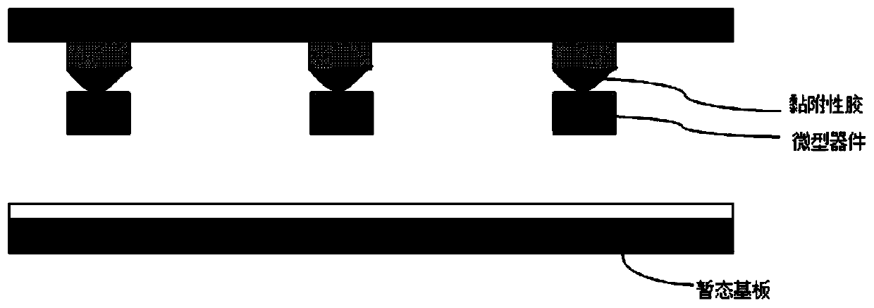
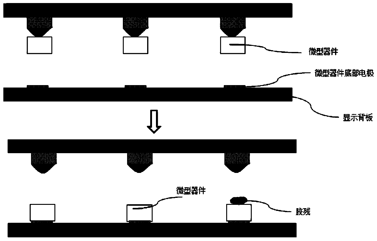
In the actual operation process, the adhesiveness of the glue is difficult to control, and the adhesion between the micro-devices and the buffer layer will be different. If the adhesion between some micro-devices and the buffer layer is strong, the micro-devices may not be glued. , the final result is as figure 2 As shown, most of the micro-devices are stuck, but there are still some micro-devices that have not been transferred and remain on the transient substrate
[0006] Since the adhesiveness of the glue is difficult to control, how to use the glue tip to place all the micro devices on the display backplane or the target circuit has become a difficult problem, and in the process of placing the micro devices, there may be glue residue on the adhesive surface of the micro devices ,like image 3 As shown, these residual glue may lead to LED disconnection during the top electrode process of the post-production process; in addition, the glue tip is not reusable and needs to be re-glued before it can continue to be used. These factors make the glue tip poor in utilization and transfer rate. Low level defects

Method used


Image

  • Micro device vacuum suction head and method for transferring micro device
  • Micro device vacuum suction head and method for transferring micro device
  • Micro device vacuum suction head and method for transferring micro device

Examples


Embodiment Construction

[0035] In order to more clearly illustrate the embodiments of the present invention or the technical solutions in the prior art, the specific implementation manners of the present invention will be described below with reference to the accompanying drawings. Obviously, the accompanying drawings in the following description are only some embodiments of the present invention, and those skilled in the art can obtain other accompanying drawings based on these drawings and obtain other implementations.

[0036] In order to make the drawing concise, each drawing only schematically shows the parts related to the present invention, and they do not represent the actual structure of the product. In addition, to make the drawings concise and easy to understand, in some drawings, only one of the components having the same structure or function is schematically shown, or only one of them is marked. Herein, "a" not only means "only one", but also means "more than one".

[0037] The techni...


PUM


Abstract

The invention provides a micro device vacuum suction head and a method for transferring a micro device and relates to the technical field of a micro light emitting diode. The micro device vacuum suction head includes a vacuum cavity with an air pump port and an air inlet, a base substrate with an array pattern, and a fall prevention ring located below the base substrate in order from top to bottom, wherein the array pattern is multiple circular stages, each circular stage is provided with a groove, and the groove has at least one micro through hole which penetrates through the base substrate and communicates with the vacuum cavity. The micro device vacuum suction head is advantaged in that the vacuum transfer head structure of a micro device is designed by using the principle of vacuum absorption so as to achieve huge transfer of micro devices, and thereby production cost is reduced.

Description

technical field [0001] The invention belongs to the technical field of micro-light emitting diodes, and in particular relates to a vacuum suction head for micro-devices and a transfer method for micro-devices. [0002] technical background [0003] With the vigorous development of the display industry, Micro LED (miniature light-emitting diode) has entered the stage of the times as a new generation of display technology. Compared with the existing OLED and LCD technology, Micro LED has higher brightness, lower power consumption, and better luminous efficiency. The lifespan is longer, but there are still many problems to be solved in Micro LED. Whether it is process technology, inspection standards, or manufacturing costs, there is a long distance from mass production and commercial applications, and one of the most important challenges , is how to implant a huge amount of Micro LED devices (micro devices) on the target substrate or circuit to reduce its manufacturing cost, an...

Claims


Application Information

Patent Timeline
Patent Type & Authority Applications(China)
IPC IPC(8): H01L21/683H01L21/677H01L27/15
CPCH01L21/677H01L21/6838H01L27/156
Inventor 黄安郁杰朱充沛高威安金鑫
Owner NANJING CEC PANDA LCD TECH
Why Eureka
Try Eureka