
Base station

A technology of base station and cleaning tank, which is applied in cleaning carpets, floors, cleaning equipment, etc. It can solve the problems of difficult cleaning, inconvenient cleaning, complex base station structure, etc., and achieve the effect of improving user experience

Pending Publication Date: 2019-11-19
NARWEL INTELLIGENCE TECH CO LTD
View PDF0 Cites 25 Cited by
  • Summary
  • Abstract
  • Description
  • Claims
  • Application Information

AI Technical Summary

Problems solved by technology

[0004] The technical problem to be solved by the present invention is to provide a base station for the technical problem that the internal structure of the existing base station is complex, resulting in inconvenient and difficult cleaning.

Method used


Image

  • Base station
  • Base station
  • Base station

Examples


no. 1 example

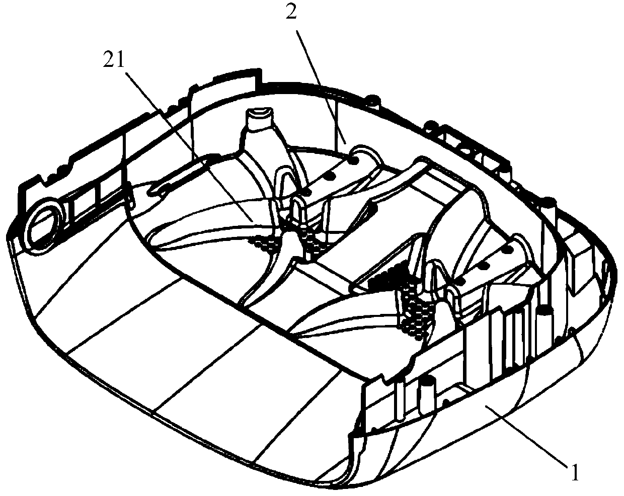
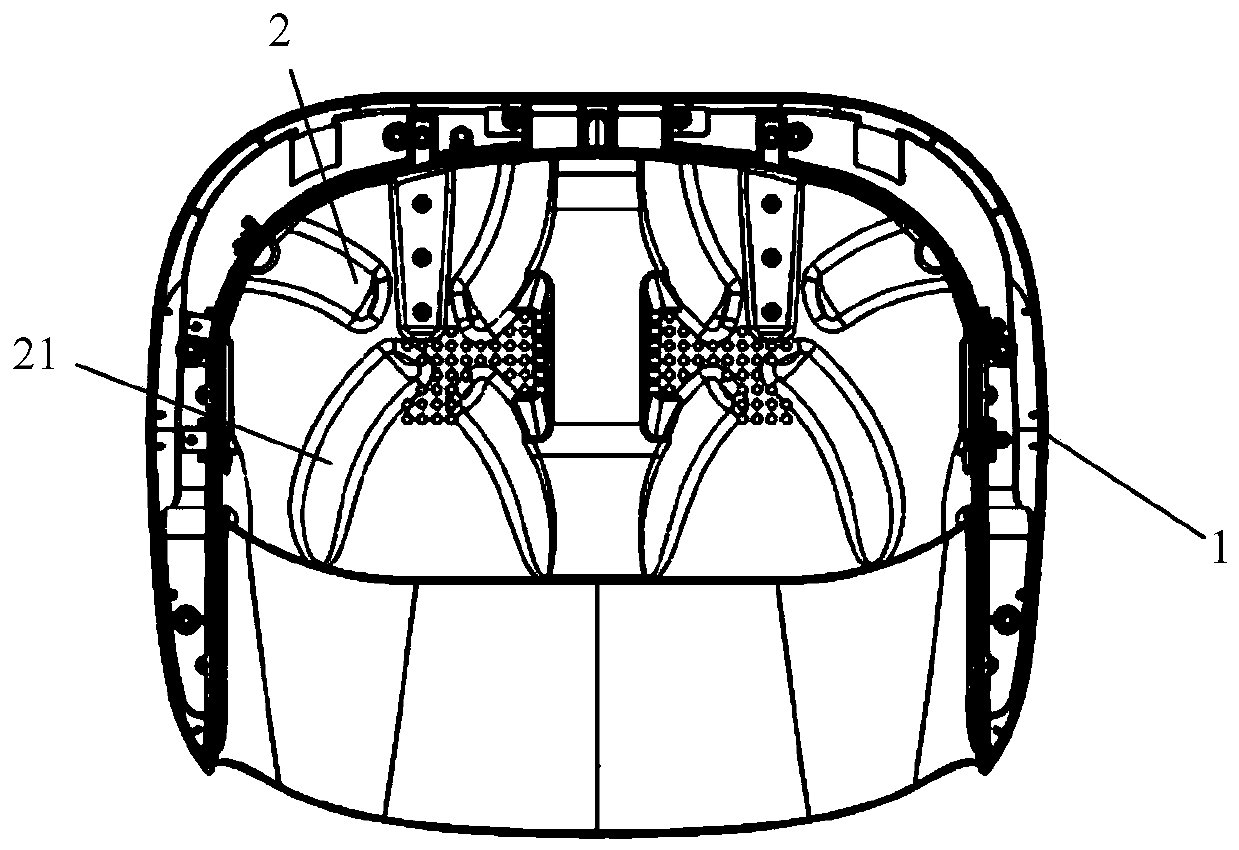
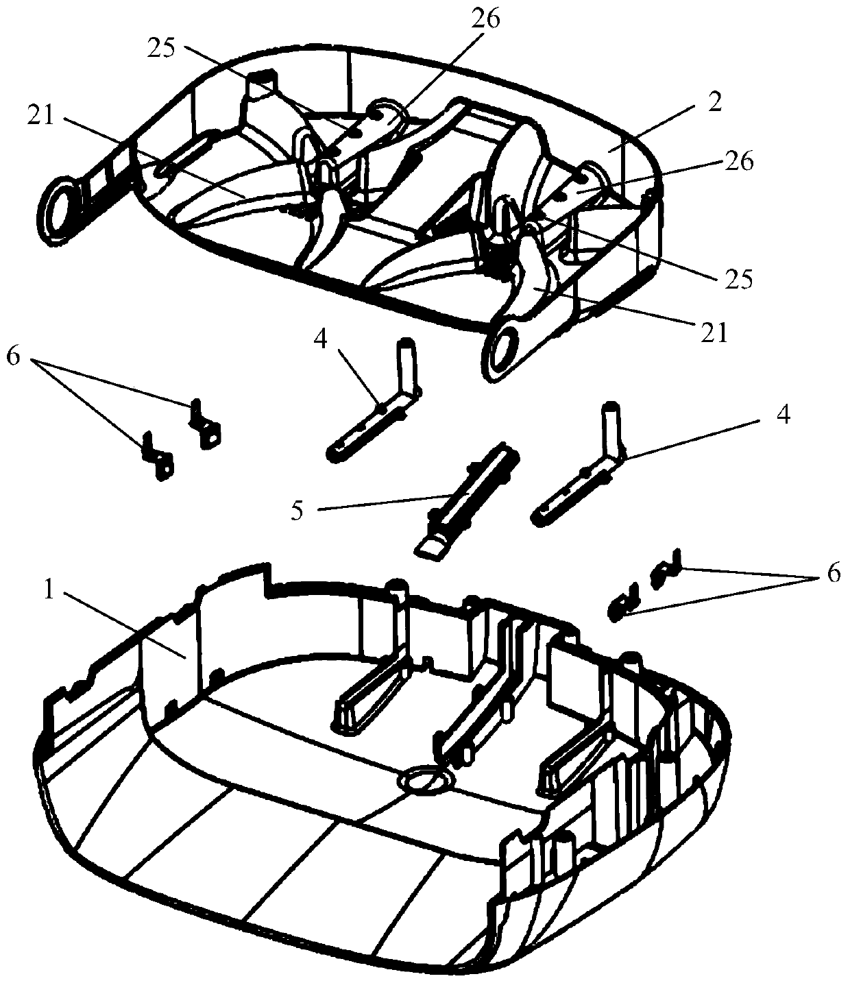
[0077] Such as Figure 1 to Figure 17 The base station of the first embodiment of the present invention is shown.

[0078] Such as Figure 1 to Figure 4 As shown, the base station includes a base station base 1 and a cleaning tank 2. The cleaning tank 2 is arranged above the base station base 1. The cleaning tank 2 is provided with a liquid inlet structure, a liquid discharge structure, and a raised portion 21. The raised portion 21 is used for cleaning Clean the mopping parts of the robot for scraping and decontamination. A sewage collecting cavity is formed between the base station base 1 and the cleaning tank 2, and the draining structure communicates with the sewage collecting cavity. Among them, the liquid inlet structure is used to provide cleaning water to the cleaning tank 2, and the liquid discharge structure is used to discharge the cleaning water in the cleaning tank 2 out of the cleaning tank 2, for example, the cleaning water after cleaning the mopping parts of ...

no. 2 example

[0122] Figure 18 Shown is the base station provided by the second embodiment of the present invention. The difference from the first embodiment is that the anti-overflow contact piece 6 is installed on the base station base 1 , and the anti-overflow water port 28 in the first embodiment is no longer provided on the cleaning tank 2 . The sewage is filtered through the cleaning tank 2 and flows into the base station base 1. When there is a problem with water absorption, the water will gradually overflow and soak into the anti-overflow contact piece 6, thereby realizing the anti-overflow function of the base station.

[0123] For example, the anti-overflow contact piece 6 is arranged in the sewage collection chamber and on the inner side wall of the base station base 1 . In the vertical direction, the anti-overflow contact piece 6 is located below the overflow water level of the base station base 1 and above the lowest point of the water level of the base station base 1 .

[0...

no. 3 example

[0127] Figure 19 to Figure 22 Shown is the base station provided by the third embodiment of the present invention. The base station in the third embodiment of the present invention can be implemented based on any one of the above-mentioned embodiments 1 to 2, and the base station in the third embodiment of the present invention further includes a box 9 . The base station base 1 includes a base groove 11, a groove wall 12 arranged on a side of the base groove 11, a guide surface 13 extending downward from one side of the base groove 11, and guide surfaces arranged on both sides of the guide surface 13. Plate 14, box body 9 is connected with groove wall 12 and guide plate 14. The box body 9 and the base station base 1 form a cavity structure, and the cavity structure includes a base station entrance 15 on a side close to the guide surface 13, and the cleaning tank 2 is located in the cavity structure. The cleaning tank 2 includes a tank body 22 and a handle 23 , the tank body...


PUM


Abstract

The invention belongs to the technical field of cleaning equipment, and relates to a base station. The base station comprises a base station foundation and a cleaning tank, wherein the cleaning tank is arranged above the base station foundation; a liquid inlet structure, a liquid outlet structure and a protruding part are arranged on the cleaning tank; the protruding part is used for scraping anddecontaminating a mopping and wiping part of a cleaning robot; a sewage collecting cavity is formed between the base station foundation and the cleaning tank; and the liquid outlet structure communicates with the sewage collecting cavity. According to the base station, rubbish of the mapping and wiping part is scraped by the protruding part on the cleaning tank and falls into the cleaning tank, and sewage flows into the sewage collecting cavity formed between the base station foundation and the cleaning tank through the liquid outlet structure. After the cleaning is completed, the rubbish on the cleaning tank can be cleaned; and the base station is convenient to clean and low in cleaning difficulty, so that the user experience is improved.

Description

technical field [0001] The invention belongs to the technical field of cleaning equipment, and in particular relates to a base station. Background technique [0002] The base station is a device used to clean the mopping parts of the cleaning robot or provide charging services for the cleaning robot. [0003] At present, some cleaning equipment (cleaning robots) on the market will clean their own mopping parts on the cleaning tank of the base station, but after the cleaning equipment has cleaned the mopping parts for a long time, some garbage will be deposited on the cleaning tank. It is convenient for handling and cleaning, and the internal structure of the base station is complex and inconvenient to clean, so it will increase the difficulty of cleaning and reduce the user experience. Contents of the invention [0004] The technical problem to be solved by the present invention is to provide a base station for the existing technical problems that the internal structure o...

Claims


Application Information

Patent Timeline
IPC IPC(8): A47L11/40
CPCA47L11/4091A47L2201/02
Inventor 张峻彬黄吉彪林伟劲
Owner NARWEL INTELLIGENCE TECH CO LTD
Learn More