Automatic ball loading device for sliding rail

A bead-loading and automatic technology, applied in metal processing, metal processing equipment, manufacturing tools, etc., can solve the problems of low assembly efficiency, poor assembly quality, large labor consumption, etc., to improve processing stability, reduce production costs, The effect of improving production efficiency

Active Publication Date: 2019-11-19
昆山棠赢电子科技有限公司
View PDF4 Cites 2 Cited by
  • Summary
  • Abstract
  • Description
  • Claims
  • Application Information

AI Technical Summary

Problems solved by technology

However, manual operation has the disadvantages of weak assembly stability and poor assembly quality, which greatly affects the normal use of the slide rail after assembly
In addition, due to the large difference in the size of the components in the slide rail, it is very easy to have missing parts and misplaced parts during the assembly process.
Especially for the riveting of some parts, because the riveting part is relatively small, it is difficult to realize automatic riveting on traditional processing machines
In addition, manual assembly requires a lot of labor, and its assembly efficiency is low, thereby increasing the processing cost of the slide rail
Therefore, the traditional slide rail assembly method still needs to be further improved

Method used


Image

  • Automatic ball loading device for sliding rail
  • Automatic ball loading device for sliding rail
  • Automatic ball loading device for sliding rail

Examples


Embodiment 1

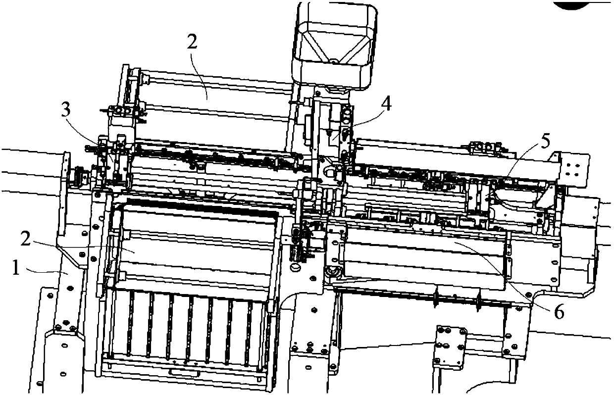
[0033] Embodiment 1: An automatic bead loading device for slide rails, including a frame 1, a feeding inclined bucket 2, a bead pushing mechanism 3, a steel ball feeding mechanism 4, a bead pushing mechanism 5 and a material distributing mechanism 6 , the feeding inclined bucket 2 is obliquely installed on the side of the frame 1, the bead pushing mechanism 3 and the bead pushing mechanism 5 are installed above the frame 1 and are respectively located at both ends of the frame 1, and the steel ball feeding The mechanism 4 is fixedly installed above the frame 1 and is located between the bead push-in mechanism 3 and the bead push-out mechanism 5, and the material distribution mechanism 6 is installed on the frame 1 and is located at one end of the bead push-out mechanism 5;

[0034] The bead pushing mechanism 3 further includes a feeding motor 1b, a feeding screw mandrel 2b, a feeding movable block 3b and a feeding cylinder 4b. One end face, the rotating shaft of the feeding mo...

Embodiment 2

[0042] Embodiment 2: An automatic bead loading device for slide rails, including a frame 1, a feeding inclined bucket 2, a bead pushing mechanism 3, a steel ball feeding mechanism 4, a bead pushing mechanism 5 and a material distributing mechanism 6 , the feeding inclined bucket 2 is obliquely installed on the side of the frame 1, the bead pushing mechanism 3 and the bead pushing mechanism 5 are installed above the frame 1 and are respectively located at both ends of the frame 1, and the steel ball feeding The mechanism 4 is fixedly installed above the frame 1 and is located between the bead push-in mechanism 3 and the bead push-out mechanism 5, and the material distribution mechanism 6 is installed on the frame 1 and is located at one end of the bead push-out mechanism 5;

[0043] The bead pushing mechanism 3 further includes a feeding motor 1b, a feeding screw mandrel 2b, a feeding movable block 3b and a feeding cylinder 4b. One end face, the rotating shaft of the feeding mo...


PUM


Abstract

The invention discloses an automatic ball loading device for a sliding rail. The automatic ball loading device comprises a rack, a loading inclined hopper, a ball strip pushing-in mechanism, a steel ball feeding mechanism, a ball strip pushing-out mechanism and a material distributing mechanism. The loading inclined hopper is obliquely arranged on the side surface of the rack. The ball strip pushing-in mechanism and the ball strip pushing-out mechanism are arranged above the rack and located at the two ends of the rack correspondingly. The material distributing mechanism is arranged on the rack and is positioned at one end of the ball strip pushing-out mechanism. A discharging motor is arranged on the end surface of one end, far away from the loading inclined hopper, of the rack. A plurality of gas holes are connected with a plurality of blowing nozzles correspondingly. A steel ball mounting mechanism is provided with a through ball mounting hole. One end of the ball mounting hole is connected with the steel ball feeding mechanism through a ball feeding leather hose. A ball outlet is formed in the other end of the ball mounting hole. An air blowing hole is formed above one end, connected with the steel ball feeding mechanism, of the ball mounting hole. A ball blocking mechanism is arranged below the ball outlet of the ball mounting hole. According to the automatic ball loadingdevice, due to the arrangement of a wedge-shaped strip, a steel ball can be better squeezed into a ball groove of a feeding belt, and simpleness, convenience and good effect are realized.

Description

technical field [0001] The invention relates to an automatic bead loading device for slide rails, and belongs to the technical field of automatic processing. Background technique [0002] The slide rail is a movable connecting part of a household drawer or panel that is widely used at present. It utilizes the mutual sliding of the movable rail and the fixed rail to realize the drawing and pushing of the drawer or the panel. Since the slide rail itself has many parts, and its assembly requires means such as riveting, plugging, snapping, etc., the existing slide rail installation is usually based on manual installation. However, manual operation has the disadvantages of weak assembly stability and poor assembly quality, which greatly affects the normal use of the slide rail after assembly. In addition, due to the large differences in the size of the parts in the slide rail, it is very easy to have missing parts and misplaced parts during the assembly process. Especially for ...

Claims


Application Information

Patent Timeline
Patent Type & Authority Applications(China)
IPC IPC(8): B23P19/00
CPCB23P19/00B23P19/001B23P19/005
Inventor 杨家荣沈雷张庆文
Owner 昆山棠赢电子科技有限公司
Why Eureka
Try Eureka