
Flexible component mounting equipment

A technology for assembling equipment and flexible parts, which is applied in the field of automated machinery and equipment, and can solve the problems of low paste efficiency and poor precision

Pending Publication Date: 2019-11-19
JIANGSU JINMING IND ROBOT AUTOMATION
View PDF5 Cites 1 Cited by
  • Summary
  • Abstract
  • Description
  • Claims
  • Application Information

AI Technical Summary

Problems solved by technology

[0009] The purpose of the present invention is to provide an assembly device for flexible parts, in order to solve the problems of low paste efficiency and poor precision in the prior art

Method used


Image

  • Flexible component mounting equipment
  • Flexible component mounting equipment
  • Flexible component mounting equipment

Examples


Embodiment Construction

[0080] The invention will be further described below in conjunction with the accompanying drawings and specific embodiments.

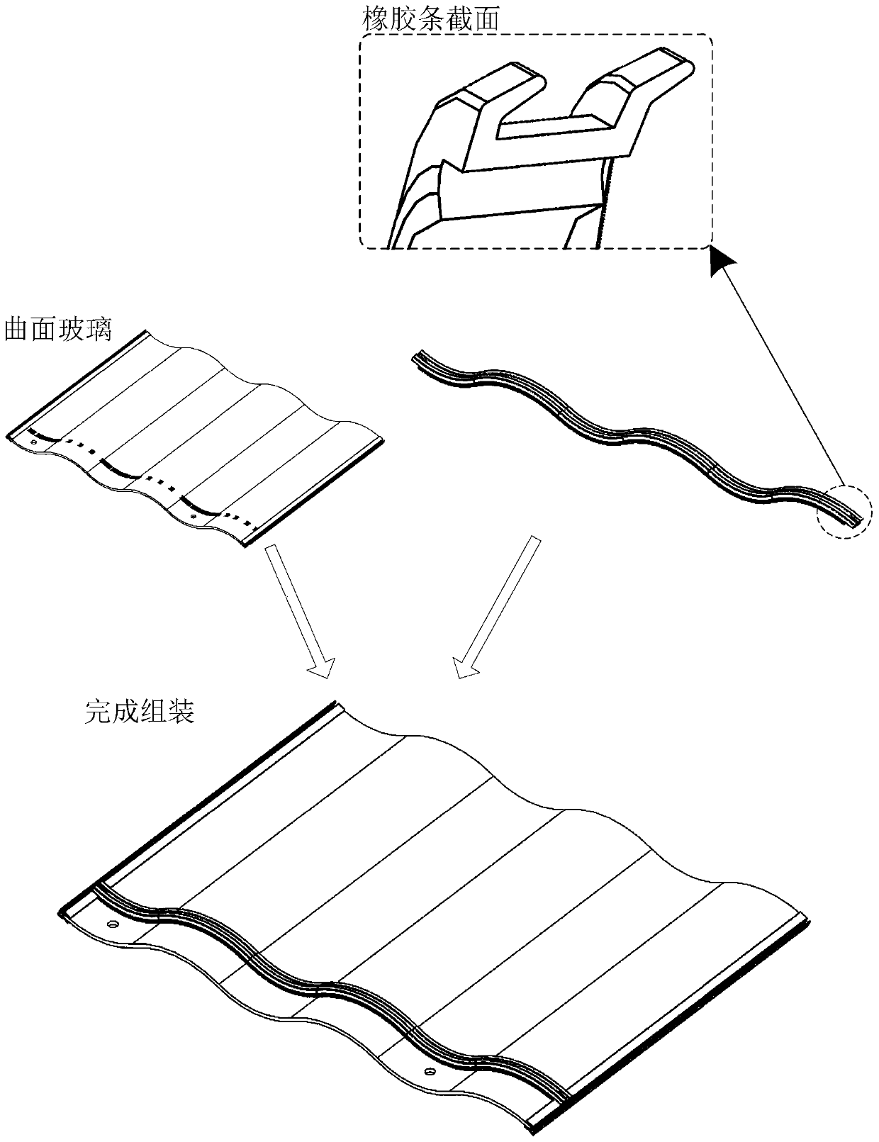
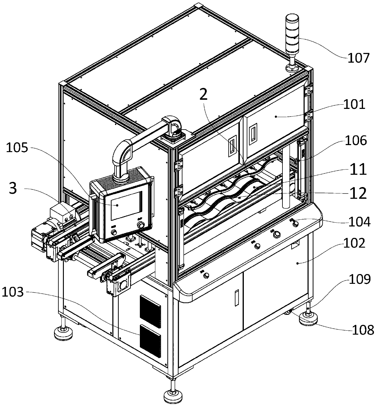
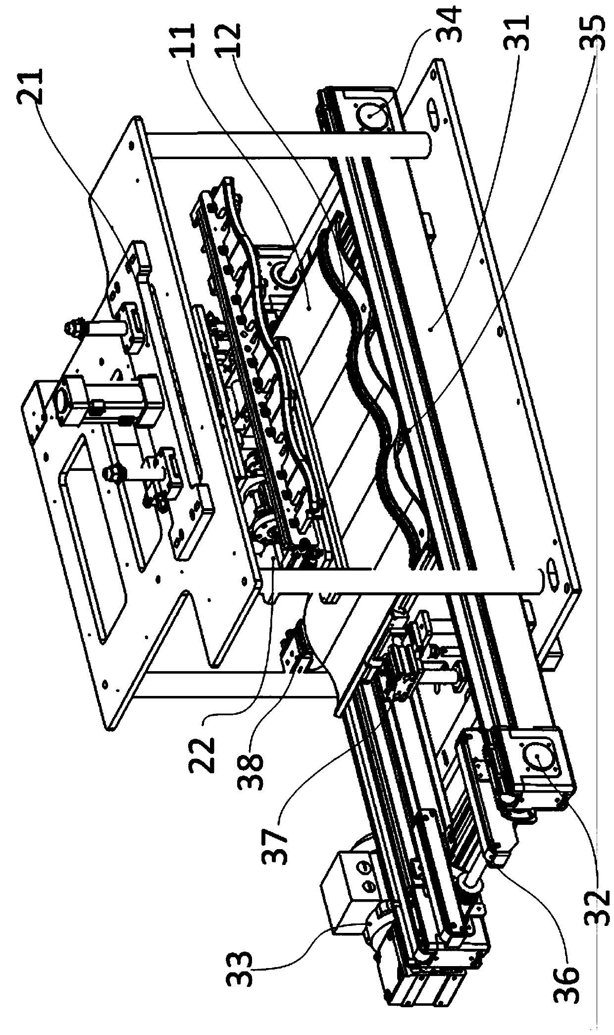
[0081] Such as figure 2 As shown, it is a schematic diagram of the overall appearance of the flexible component assembly equipment of the present invention, which is an independent automatic assembly equipment, including an external chassis, a frame, a control system, and an internal mechanical actuator; 11 in the figure is a flexible rubber strip to be pasted Curved glass, 12 is a flexible rubber strip; above the curved glass 11 is provided with a pasting actuator 2, and the curved glass 11 is placed on the conveyor 3; the pasting actuator 2 and conveyor 3 are installed on the equipment On the rack, the equipment rack is also equipped with:

[0082] (1) The upper frame 101 located above the equipment frame is used to set up and fix the pasting actuator 2;

[0083] (2) The lower frame 102 positioned below the equipment frame is used to set up and fi...


PUM


Abstract

The invention relates to flexible component mounting equipment. Particularly, flexible rubber bars are bonded to curved surface glass. The flexible component mounting equipment comprises a case, a rack, a control system and an internal mechanical executing mechanism, wherein the case, the rack and the control system are located outside. The flexible component mounting equipment is characterized inthat the internal mechanical executing mechanism is installed on the equipment rack; the internal mechanical executing mechanism comprises a bonding executing mechanism and a conveyor; and the bonding executing mechanism comprises a rubber bar pressing-down mechanism. According to the flexible component mounting equipment, for the demands for bonding flexible rubber bars on curved surface glass,automatic equipment is adopted, and semi-automation of work is achieved; the flexible component mounting equipment is high in automation degree, bonding efficiency, precision and consistency; and theflexible component mounting equipment greatly reduces the labor intensity of workers, and improves operation reliability and operation efficiency.

Description

technical field [0001] The invention relates to a special equipment for installing flexible components on curved glass, in particular flexible rubber strips, which belongs to the field of automatic mechanical equipment. Background technique [0002] Flexible parts are often seen in our real life, such as cloth, flexible rubber pads for cushioning, sealing strips, protective covers, etc. Their commonality is deformation, and it is irregular deformation, whether it is due to external force, temperature, humidity, etc. All will be deformed, and some parts will also deform irregularly under the condition of their own gravity, which makes the assembly of such parts mostly manual. [0003] With the development of technology, in order to pursue a more beautiful effect, curved glass is more and more widely used, such as a kind of colored tile whose Chinese patent publication number is CN109301013A, a kind of solar module and its preparation method whose Chinese patent publication nu...

Claims


Application Information

Patent Timeline
Patent Type & Authority Applications(China)
IPC IPC(8): B29C65/48B29C65/78B29C65/80B29C65/00
CPCB29C65/48B29C65/7805B29C65/7841B29C65/7847B29C65/80B29C66/7465
Inventor 袁培荣王光旭卢浩良尚海军杨怀亚仓浪朱永清
Owner JIANGSU JINMING IND ROBOT AUTOMATION
Learn More