Automatic concrete pouring device for building construction

A construction and automatic pouring technology, applied in the direction of construction and building structure, can solve the problems of small scope, poor stability, scratching damage, etc., and achieve the effect of pouring concrete evenly, reducing friction loss, and adjusting the movement smoothly.

Active Publication Date: 2020-06-02
东莞市交港建材有限公司
View PDF6 Cites 1 Cited by
  • Summary
  • Abstract
  • Description
  • Claims
  • Application Information

AI Technical Summary

Problems solved by technology

[0004] The purpose of the present invention is to solve the problem that the existing building construction concrete pouring device pours concrete on the construction ground not uniformly and comprehensively; Some components on the pouring device have poor stability when being adjusted and moved, and the pouring cylinder used for pouring concrete is not smooth and reliable when the working position is adjusted; the overall service life of the device is low, and the range that the pouring device can cover when it is working It is not convenient and flexible for the staff to adjust the working position of the pouring device; and the working distance between the pouring device and the construction ground of different heights cannot be flexibly adjusted; resulting in the pouring of concrete by the pouring device on the construction ground of different heights, The height is not accurate and suitable; and the parts on the pouring device are easy to be scratched and damaged with the construction ground when they are movable, and the stability of the pouring device is poor when working. Therefore, an automatic concrete pouring device for building construction is proposed

Method used


Image

  • Automatic concrete pouring device for building construction
  • Automatic concrete pouring device for building construction
  • Automatic concrete pouring device for building construction

Examples


Embodiment Construction

[0050] The technical solutions of the present invention will be clearly and completely described below in conjunction with the embodiments. Apparently, the described embodiments are only some of the embodiments of the present invention, not all of them. Based on the embodiments of the present invention, all other embodiments obtained by persons of ordinary skill in the art without creative efforts fall within the protection scope of the present invention.

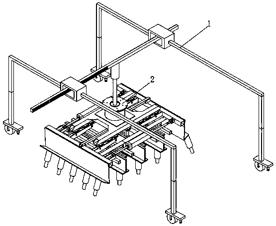
[0051] see Figure 1-14 As shown, an automatic concrete pouring device for building construction includes a loading frame 1 and a pouring tray 2, and a pouring tray 2 is arranged under the middle part of the loading frame 1;

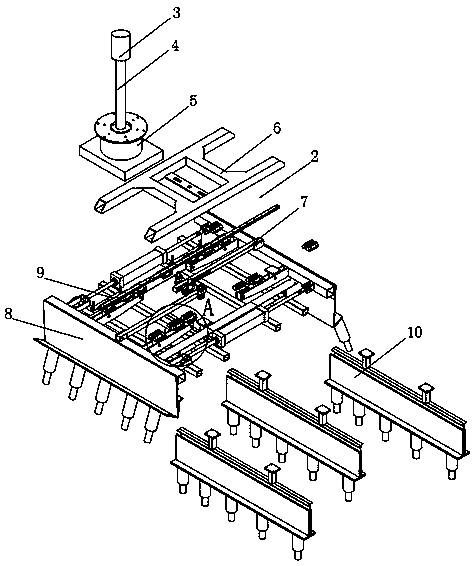
[0052] The top of the pouring tray 2 is provided with a motor one 3, and the bottom of the motor one 3 is rotated and connected with a rotating shaft one 4, the bottom of the rotating shaft one 4 is provided with a motor two 5, and the bottom of the motor two 5 is provided with a set plate 6, and the ...


PUM


Abstract

The invention discloses an automatic pouring device for building construction concrete. The automatic pouring device comprises a loading frame and a pouring plate. The pouring plate is arranged belowthe middle portion of the loading frame. The top of the pouring plate is provided with a motor I. A rotating shaft I is rotatably connected below the motor I. The automatic pouring device has the beneficial effects that a plurality of pouring bases are arranged on a side mounting table and an inner mounting table, concrete is synchronously discharged from the pouring bases for pouring, and the plurality of pouring bases are distributed at equal intervals; therefore, on one hand, the device ensures concrete poured onto the construction ground with better uniformity and comprehensiveness, and the working efficiency of the device is improved; on the other hand, it is ensured that the device is better in efficiency and saves more time and labor when the device is used for pouring the concrete;and when the pouring plate is used for concrete pouring, a dragging rod II and the pouring plate are driven to be adjusted and move left and right, so that on the one hand, the working range of the device for pouring the concrete is expanded, and on the other hand, workers can adjust the working position of the pouring plate more conveniently and quickly, and it is ensured that the pouring platecan be used for pouring the concrete more uniformly.

Description

technical field [0001] The invention relates to a pouring device, in particular to an automatic concrete pouring device for building construction, and belongs to the technical field of protection device applications. Background technique [0002] With the rapid development of people's living standards, concrete pouring devices are used more and more frequently in the construction field. The main function of concrete pouring devices is to pour concrete on the construction ground, so that the staff can spread and shape the concrete on the construction ground. . [0003] The existing concrete pouring device for building construction still has many deficiencies in use. The existing concrete pouring device for building construction pours concrete on the construction ground not uniformly and comprehensively, and the working efficiency of the pouring device is slow, and the work is difficult. When the degree of automation is high, the use is not enough to save time and effort. The...

Claims


Application Information

Patent Timeline
Patent Type & Authority Patents(China)
IPC IPC(8): E04F21/24
CPCE04F21/24
Inventor 夏杏军张健钟灿坚
Owner 东莞市交港建材有限公司
Why Eureka
Try Eureka