A Visual Analysis Method for Lubricating Fluid Injection Porous Surface Damage
A technology of porous surface and analysis method, applied in the direction of optical testing flaws/defects, etc., can solve the problems of limited application scenarios, fluid properties, easy loss of lubricating fluid, damaged surface properties, etc., to achieve the effect of speeding up the test rate
- Summary
- Abstract
- Description
- Claims
- Application Information
AI Technical Summary
Problems solved by technology
Method used
Image
Examples
Embodiment 1
[0040] A visual analysis method for lubricating fluid injected porous surface damage, including 5 steps:
[0041] Step 1: Dyeing of the water
[0042] Adjust the pH value of the water to between 2 and 12, add water-soluble dyes to the water so that the concentration of the dyes in the water is 0.001% to 5%, and stabilize the temperature of the aqueous solution at 0 to 50°C;
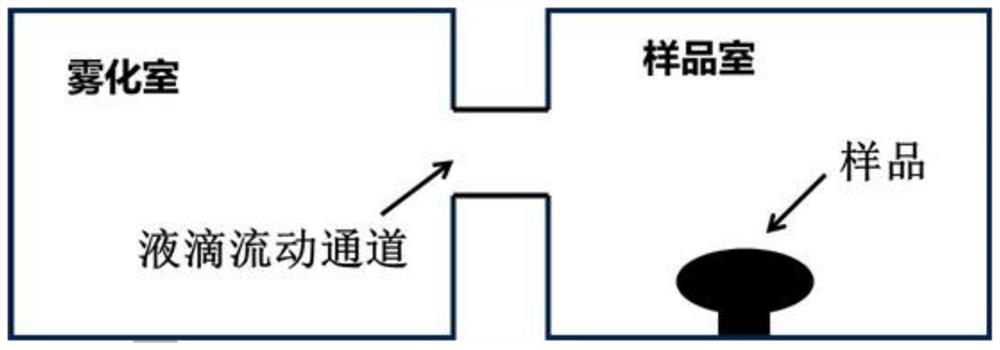
[0043] Step 2: Atomization
[0044] Atomize the dyeing water configured above, the temperature of the atomization chamber is 0-40°C, and the diameter of the atomized water droplets is controlled between 1 μm and 1 mm;
[0045] Step 3: Coverage of the droplet on the surface of the sample to be tested
[0046] Introduce the atomized water droplets around the sample to be tested, and the droplets will adhere to the surface of the sample after hitting the surface. 2μm~2mm, and avoid small droplets adhering to the sample surface from aggregating into large droplets;
[0047] Step 4: Freeze
[0048] Put th...
Embodiment 2
[0052] This example is basically the same as Example 1, except that the dye used in step 1 is 0.5% phenolphthalein, the pH value of the aqueous solution is adjusted to 9, and the indication of the color of the damaged area is that the surface color changes to bright red only in the center of the droplet A small amount of dark red, the area where the color changes is the surface damage area, and the area damage rate of the surface is about 20%;
[0053] Technical description of this embodiment: This embodiment uses an alkaline solution, so that some samples that cannot be tested in an acidic or neutral environment can be tested. This embodiment is suitable for surfaces tested in an alkaline environment, which expands its application range .
Embodiment 3
[0055] This example is basically the same as Example 1, except that the dye used in step 1 is 0.3% phenol red, the pH value of the aqueous solution is adjusted to 6, and the indication of the color of the damaged area is that the color changes from yellow to only in the center of the droplet The dark yellow, the color-changing area is the surface damage area, and the area damage rate of the surface is about 25%;
[0056] Technical description of this embodiment: This embodiment uses an acidic solution, so that some samples that are not suitable for testing in an acidic or neutral environment can be tested, and the application range of this method can be expanded.
PUM
| Property | Measurement | Unit |
|---|---|---|
| diameter | aaaaa | aaaaa |
| diameter | aaaaa | aaaaa |
| diameter | aaaaa | aaaaa |
Abstract
Description
Claims
Application Information
 - R&D
- Intellectual Property
- Life Sciences
- Materials
- Tech Scout
- Unparalleled Data Quality
- Higher Quality Content
- 60% Fewer Hallucinations
Browse by: Latest US Patents, China's latest patents, Technical Efficacy Thesaurus, Application Domain, Technology Topic, Popular Technical Reports.
© 2025 PatSnap. All rights reserved.Legal|Privacy policy|Modern Slavery Act Transparency Statement|Sitemap|About US| Contact US: help@patsnap.com


