Artificial potential field method-based machine obstacle avoidance method and device

An artificial potential field method and artificial potential field technology, applied in two-dimensional position/channel control and other directions to achieve the effect of increasing the gravitational potential field

Active Publication Date: 2019-11-19
SUZHOU LANGCHAO INTELLIGENT TECH CO LTD
View PDF2 Cites 2 Cited by
  • Summary
  • Abstract
  • Description
  • Claims
  • Application Information

AI Technical Summary

Problems solved by technology

[0005] In order to solve the above-mentioned technical problems existing in the prior art, this application provides a machine obstacle a

Method used


Image

  • Artificial potential field method-based machine obstacle avoidance method and device
  • Artificial potential field method-based machine obstacle avoidance method and device
  • Artificial potential field method-based machine obstacle avoidance method and device

Examples


Embodiment 1

[0043] Embodiment 1 of the present application provides a machine obstacle avoidance method based on the artificial potential field method, which will be described in detail below with reference to the accompanying drawings.

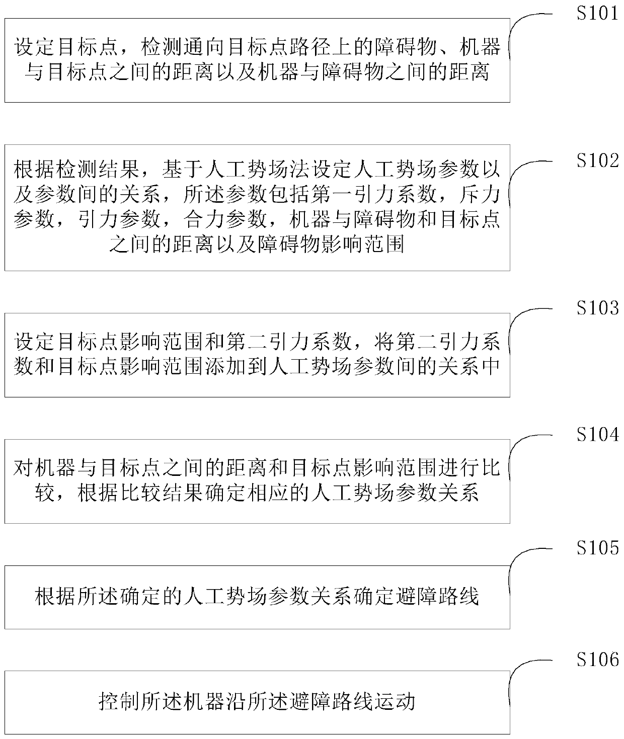
[0044] see figure 1 , which is a flow chart of the method for avoiding obstacles of a machine based on the artificial potential field method provided in Embodiment 1 of the present application.

[0045] The method described in Embodiment 1 of the present application includes the following steps:

[0046] Step S101: Set a target point, and detect obstacles on the path leading to the target point, the distance between the machine and the target point, and the distance between the machine and the obstacle.

[0047] Step S102: According to the detection results, set the parameters of the artificial potential field and the relationship between the parameters based on the artificial potential field method. The distance between them and the range of influence...

Embodiment 2

[0072] Based on the machine obstacle avoidance method based on the artificial potential field method provided in the above embodiments, Embodiment 2 of the present application also provides another example of an obstacle avoidance method based on the artificial potential field method, which will be described in detail below with reference to the accompanying drawings.

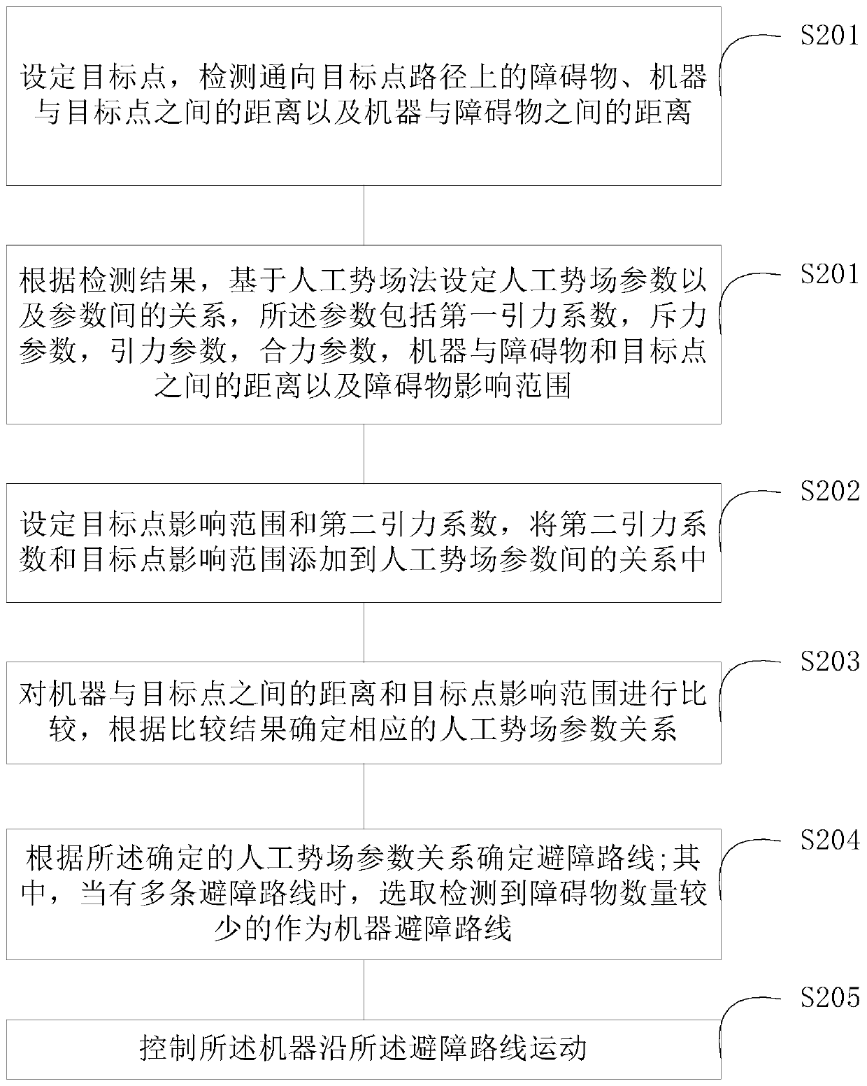
[0073] see figure 2 , which is a flow chart of another machine obstacle avoidance method based on the artificial potential field method provided in Embodiment 2 of the present application.

[0074] Embodiment 2 of the present application includes the following steps:

[0075] S201-S203 are the same as S101-S103 in the first embodiment.

[0076] S204: Determine an obstacle avoidance route according to the determined artificial potential field parameter relationship; wherein, when there are multiple obstacle avoidance routes, select the one with fewer detected obstacles as the machine obstacle avoidance route. ...

Embodiment 3

[0080] Based on the machine obstacle avoidance method based on the artificial potential field method provided in the above embodiments, Embodiment 3 of the present application also provides a test platform for the machine obstacle avoidance method based on the artificial potential field method.

[0081] see Figure 4 , which is a flow chart of building a test platform for a machine obstacle avoidance method based on the artificial potential field method provided in Embodiment 3 of the present application. The specific steps are as follows:

[0082] Step S301: Select a suitable hardware assembly machine, including a machine system, a control system and a power system.

[0083] Wherein, the machine system includes a machine support, etc.; the control system includes a motion control board, a starting base station, a remote controller, and a receiver; and the power system includes a battery, a motor, and the like.

[0084] Step S302: Select an image detection device. In this sys...


PUM


Abstract

The embodiments of the invention disclose an artificial potential field method-based machine obstacle avoidance method and device. With the method and device adopted, a GNRON problem in a machine obstacle avoidance technology can be solved. The method comprises the following steps that: a target point is set, and an obstacle which is located on a path leading to the target point, a distance between a machine and the target point, and a distance between the machine and the obstacle are detected; artificial potential field parameters and relations between the artificial potential field parameters are set based on an artificial potential field method according to detection results, wherein the parameters comprise a first gravity coefficient, a repulsive force parameter, a gravity parameter, aresultant force parameter, the distance between the machine and the obstacle, the distance between the machine and the target point and an obstacle influence range; a target point influence range anda second gravity coefficient are set, and the second gravity coefficient and the target point influence range are added into the relations between the artificial potential field parameters; the distance between the machine and the target point is compared with the target point influence range, and corresponding artificial potential field parameters are determined according to a comparison result;an obstacle avoidance route is calculated according to the determined artificial potential field parameters; and the machine is controlled to move along the obstacle avoidance route.

Description

technical field [0001] The present application relates to the technical field of intelligent obstacle avoidance, in particular to a machine obstacle avoidance method and device. Background technique [0002] With the rapid development of intelligent machine technology, the obstacle avoidance function of machines has gradually become important in demand. With the continuous improvement of the requirements for obstacle avoidance technology, simple obstacle avoidance strategies can no longer meet the increasingly complex machine motion environment, so scholars and researchers at home and abroad have begun to develop path planning algorithms for various machine obstacle avoidance. [0003] The essence of the machine obstacle avoidance algorithm is an algorithm for path planning during the machine movement process. In the prior art, the artificial potential field method is the most common method to solve the machine obstacle avoidance problem. In the artificial potential field m...

Claims


Application Information

Patent Timeline
IPC IPC(8): G05D1/02
CPCG05D1/02
Inventor 夏方健
Owner SUZHOU LANGCHAO INTELLIGENT TECH CO LTD
Why Eureka
Try Eureka