Permanent magnet device for converting conservative field into non-conservative field
A permanent magnet device, conservative field technology, used in permanent magnets, electromechanical devices, electrical components, etc.
- Summary
- Abstract
- Description
- Claims
- Application Information
AI Technical Summary
Problems solved by technology
Method used
Image

Examples
Embodiment 1
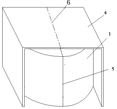
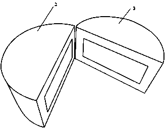
[0018] as attached figure 1 As shown, the present invention is mainly made up of permanent magnetic pole 1 and silicon steel cover 4, and the appearance shape of permanent magnetic pole 1 presents hollow cylinder shape, is formed by the permanent magnet of two hollow semi-cylindricals, one of them The hollow semi-cylindrical body is an N pole permanent magnet 2, its inner surface presents an N pole, and its outer surface presents an S pole, so its N poles all face the inner core of the permanent magnet 1, and the other hollow semi-cylindrical body is an S pole Permanent magnet 3, its inner surface presents S pole, and outer surface presents N pole, so its S pole is all towards the inner core of permanent magnetic pole 1, like this, N pole permanent magnet 2 and S pole permanent magnet 3 attract each other correspondingly. Merge into the permanent magnet pole 1 of complete hollow cylinder, the top and the bottom end of the merged permanent magnet pole 1 are all round, and the m...
Embodiment 2
[0020] Such as image 3 As shown, in this embodiment, the permanent magnet magnet pole 1 is the same as the permanent magnet magnet pole 1 of embodiment 1, and the silicon steel cover 4 is deformed into an annular shape, and 3-5 annular silicon steel covers 4 with different diameters Superimposed and fixed, the superimposed silicon steel cover 4 is fixed on the side of the permanent magnet 1 and the magnetic pole anastomosis 5 by pasting or fixing parts. In the present embodiment, the permanent magnetic pole 1 has a diameter of 12.5cm, a height of 9.4cm, and a thickness of 2.5cm. The silicon steel cover 4 is formed by stacking three silicon steel covers 4 whose diameter is larger than that of the permanent magnet 1 and whose diameter increases from inside to outside. The 4 circumferences of the inner ring silicon steel cover of the present embodiment are 75cm, the 4 circumferences of the middle ring silicon steel cover are 105cm, and the 4 circumferences of the outer ring sil...
Embodiment 3
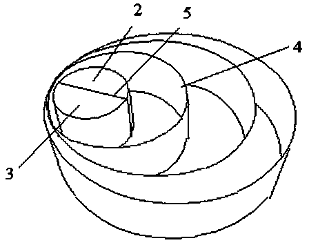
[0022] Such as Figure 4 As shown, in this embodiment, the permanent magnet pole 1 is the same as the permanent magnet pole 1 of embodiment 1, and the silicon steel cover 4 is deformed into a cup-shaped cover shape similar to that of the permanent magnet pole 1, which only has an opening at the bottom. The inner diameter of the silicon steel cover 4 is 1-2 centimeters larger than the outer diameter of the permanent magnetic pole 1, which can completely cover the permanent magnetic pole 1. In the present embodiment, the permanent magnetic pole 1 has a diameter of 12 cm, a height of 9 cm, and a thickness of 2.5 cm. , Cup-shaped silicon steel cover 4 outer diameter 15cm, high 10cm, thick 2.9mm.
PUM
| Property | Measurement | Unit |
|---|---|---|
| strength | aaaaa | aaaaa |
Abstract
Description
Claims
Application Information
 - R&D
- Intellectual Property
- Life Sciences
- Materials
- Tech Scout
- Unparalleled Data Quality
- Higher Quality Content
- 60% Fewer Hallucinations
Browse by: Latest US Patents, China's latest patents, Technical Efficacy Thesaurus, Application Domain, Technology Topic, Popular Technical Reports.
© 2025 PatSnap. All rights reserved.Legal|Privacy policy|Modern Slavery Act Transparency Statement|Sitemap|About US| Contact US: help@patsnap.com