Power industry cable deicing device

A technology of electric power industry and walking device, which is applied in the installation of cables, electrical components, overhead installation, etc. It can solve the problems of cutter ice stuck, high risk, power failure, etc., and achieve the effect of preventing internal accumulation

Active Publication Date: 2019-11-19
YIBIN POWER SUPPLY COMPANY STATE GRID SICHUAN ELECTRIC POWER
View PDF7 Cites 8 Cited by
  • Summary
  • Abstract
  • Description
  • Claims
  • Application Information

AI Technical Summary

Problems solved by technology

[0002] In cold seasons or very cold areas, ice will appear on the high-altitude cables used for power transmission. When the weight of ice on the outside of the cable exceeds the weight that the cable can bear, the cable will sag or even break, causing major damage. The power outage in the area has brought great inconvenience to the daily life of residents
Therefore, in cold seasons or regions, it is necessary to manually climb to a high altitude, and then manually remove the frozen ice layer on the outside of the cable, but manually deicing the cable is time-consuming, labor-intensive, and dangerous. high degree of work
Although there are automated cable deicing equipment, the existing cable deicing equipment generally removes the ice layer on the cable surface at one time. When the ice layer on the cable surface is thicker, it is difficult to remove the ice layer at one time. The knives used in the ice layer are easily stuck by the ice layer
Therefore, in view of the problem that the deicing cutter is easily stuck when the traditional cable deicing device removes the thicker ice layer on the cable surface, the present invention discloses a cable deicing device for the electric power industry.

Method used


Image

  • Power industry cable deicing device
  • Power industry cable deicing device
  • Power industry cable deicing device

Examples


Embodiment 1

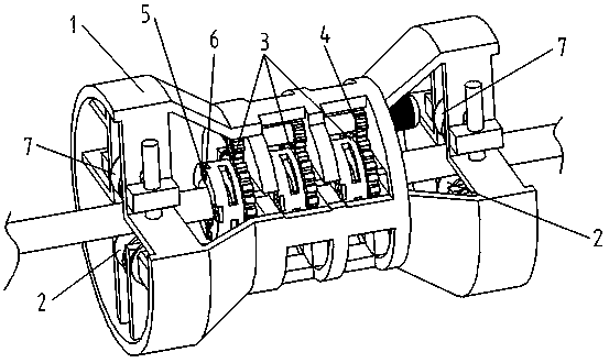
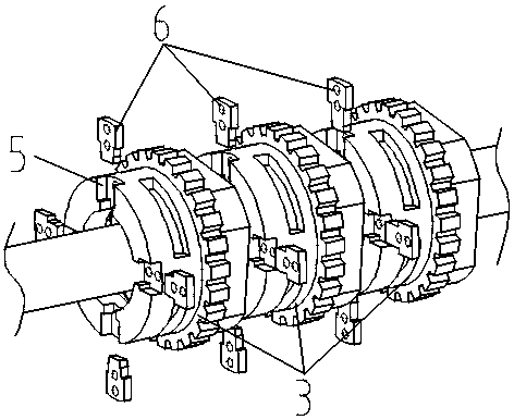
[0041] A kind of electric power industry cable deicing device of this embodiment, such as figure 1 with figure 2 As shown, it includes a mounting frame 1 set on the outside of the cable. The two ends of the mounting frame 1 are symmetrically provided with a running device 2 and a tensioning device 7. The inside of the mounting frame 1 is coaxially rotated and installed along the length direction of the cable. There are three turrets 3, the center of the turret 3 is provided with a through hole for cables to pass through, and the inside of the installation frame 1 is also equipped with a rotating device 4 that drives the turret 3 to rotate; one end of the turret 3 A number of installation grooves 5 facing the cables are arranged in a circumferential array, and deicing knives 6 are clamped in the installation grooves 5, and the distance between the deicing knives 6 arranged on the three turrets 3 and the cables moves along the The direction becomes shorter in turn.

[0042] T...

Embodiment 2

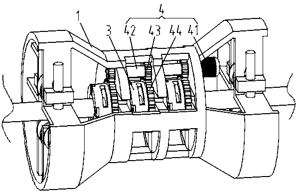
[0046] This embodiment is further optimized on the basis of embodiment 1, such as image 3 As shown, the rotating device 4 includes a rotating motor 41, a drive shaft 42, a drive gear 43, and a ring gear 44. The drive shaft 42 is installed on the inside of the installation frame 1 for rotation along the cable length direction, and the drive shaft 42 is located on the turret 3, one end of the drive shaft 42 is connected to the output end of the rotating motor 41; the outer side of the turret 3 is fitted with a ring gear 44, and the drive shaft 42 is provided with a drive gear meshed with the ring gear 44 43.

[0047] When the ice layer frozen on the outside of the cable was thicker, the deicing cutter 6 on each turret 3 required a larger cutting force when removing the ice layer. One side of the frame 3 is independently provided with a group of rotating devices 4 for driving the turret 3 to rotate. The top of the inner side of the mounting frame 1 is respectively provided wit...

Embodiment 3

[0051] This embodiment is further optimized on the basis of above-mentioned embodiment 1 or 2, such as Figure 4 with Figure 5 As shown, the interior of the installation frame 1 is coaxially provided with three sets of installation disks 11 along the length direction of the cable, and the center of the installation disk 11 is provided with a through hole for the cable to pass through; one side of the installation disk 11 is provided with There is a rotating boss, and the outer side of the rotating boss is provided with an annular rotating groove 12 along the circumferential direction, and a rotating ring 13 is arranged in the annular rotating groove 12, and a number of locking rings 13 are arranged on the outer side of the rotating ring 13 along the circumferential direction. Threaded hole 14; the turret 3 is sleeved on the outside of the swivel 13, and the position corresponding to the locking threaded hole 14 along the circumferential direction is provided with a fixing hol...


PUM


Abstract

The invention discloses a power industry cable deicing device. The device includes an installation rack sleeving the outside of a cable; the two ends of the installation rack are respectively and symmetrically provided with walking devices and tensioning devices; three rotating racks are coaxially and rotatably installed inside the installation rack in the length direction of the cable; the centers of the rotating racks are provided with through holes for the cable to pass through; a rotating device for driving the rotating racks to rotate is also installed inside the installation rack; one ends of the rotating racks are provided with multiple installation grooves facing toward the cable in a circumferential array manner; deicing cutters are clamped in the installation grooves; and the distances between the deicing cutters successively arranged on the three rotating racks and the cable are successively shortened in a movement direction. The device has beneficial effects of being high in ice layer removing efficiency and excellent in deicing effect, and can effectively prevent the deicing cutters from clamping and effectively discharge ice chips.

Description

technical field [0001] The invention belongs to the technical field of power system maintenance equipment, and in particular relates to a cable deicing device in the power industry. Background technique [0002] In cold seasons or very cold areas, ice will appear on the high-altitude cables used for power transmission. When the weight of ice on the outside of the cable exceeds the weight that the cable can bear, the cable will sag or even break, causing major damage. The power outage in the area has brought great inconvenience to the daily life of residents. Therefore, in cold seasons or regions, it is necessary to manually climb to a high altitude, and then manually remove the frozen ice layer on the outside of the cable, but manually deicing the cable is time-consuming, labor-intensive, and dangerous. Very high degree of work. Although there are automated cable deicing equipment, the existing cable deicing equipment generally removes the ice layer on the cable surface at...

Claims


Application Information

Patent Timeline
Patent Type & Authority Applications(China)
IPC IPC(8): H02G7/16
CPCH02G7/16
Inventor 杨云谢光彬
Owner YIBIN POWER SUPPLY COMPANY STATE GRID SICHUAN ELECTRIC POWER
Why Eureka
Try Eureka