Check patentability & draft patents in minutes with Patsnap Eureka AI!

Motor control device

A motor control and controller technology, applied in motor control, AC motor control, motor speed or torque control, etc., can solve problems such as large surge, inability to achieve stable control, and difficulty in obtaining a three-phase motor.

Pending Publication Date: 2019-11-19
AISIN CORP
View PDF1 Cites 0 Cited by
  • Summary
  • Abstract
  • Description
  • Claims
  • Application Information

AI Technical Summary

Problems solved by technology

However, in a three-phase motor controlled in a sensorless manner, when the energization time is extended from 120-degree energization drive, the position detection period for detecting the motor position becomes shorter, and further, the surge becomes larger, so its Unable to achieve stable control
The surge can be suppressed by SWEEP control using the duty ratio, but in some cases, it is still difficult to obtain a sufficient effect according to the rotation speed of the three-phase motor

Method used


Image

  • Motor control device
  • Motor control device
  • Motor control device

Examples


Embodiment Construction

[0019] The motor control device disclosed here is configured to have a function of suppressing a surge regardless of the rotational speed of the three-phase motor. The motor control device 1 according to the embodiment will be described below.

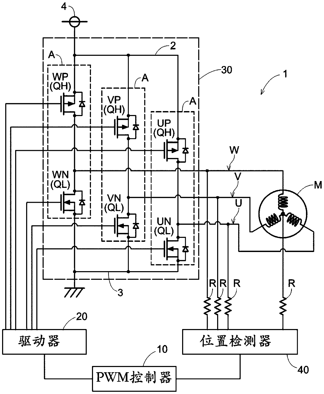
[0020] figure 1 It is a block diagram schematically illustrating the configuration of the motor control device 1 . The motor control device 1 is configured to include a PWM controller 10 , a driver 20 , an inverter 30 , and a position detector 40 .

[0021] The PWM controller 10 generates a PWM signal, and performs PWM control on an inverter 30 described below. PWM control via PWM signals is known in the related art, so details are not repeated here.

[0022] The driver 20 is provided between the PWM controller 10 and the inverter 30 , and a PWM signal generated by the PWM controller 10 is input to the driver 20 . The driver 20 improves the driving capability of the input PWM signal, and outputs the PWM signal to the inverter 30 . ...


PUM


Abstract

A motor control device (1) is provided with a motor control unit; a PWM controller (10) that performs PWM control of an inverter (30), wherein the inverter (30) drives a three-phase motor (M) and includes three arms (A), each arm portion (A) includes a high-side switching element (QH) and a low-side switching element (QL) connected in series with each other between a first power supply line (2) and a second power supply line (3), the second power supply line (3) being connected to a potential lower than a potential of the first power supply line. In an energization period and a non-energization period when the three-phase motor is energized from the first power supply line by PWM control of the inverter, the three-phase motor is energized from the second power supply line. The PWM controller performs SWEEP control of a signal applied to one of the high-side switching element and the low-side switching element and performs synchronous rectification control during a first predetermined period immediately before a transition from a power-on period to a power-on period before a non-power-on period.

Description

technical field [0001] The present disclosure relates to a motor control device having a PWM controller for PWM control of an inverter. The inverter drives a three-phase motor and includes three arms, each arm including a high-side switching element and a low-side switching element connected in series to a first power supply line and a second power supply line. Between the two power supply lines, the second power supply line is connected to a potential lower than that of the corresponding first power supply line. Background technique [0002] When a three-phase brushless motor (hereinafter referred to as "three-phase motor") is driven, pulse width modulation (PWM) control is employed in the related art. In PWM control, when the magnitude of the current (motor drive current) flowing through the three-phase motor changes suddenly, the motor torque also changes suddenly, so that noise is generated according to the sudden change in the motor torque in some cases. Therefore, te...

Claims


Application Information

Patent Timeline
IPC IPC(8): H02P6/08H02P27/08
CPCH02P6/08H02P27/08H02P2209/07H02P6/10H02P1/30H02P29/50H02P4/00
Inventor 山下谦治
Owner AISIN CORP
Features
  • R&D
  • Intellectual Property
  • Life Sciences
  • Materials
  • Tech Scout
  • Unparalleled Data Quality
  • Higher Quality Content
  • 60% Fewer Hallucinations
Learn More