Direct boost variable power generation voltage variable excitation non-isolated switch reluctance generator conversion system

A switched reluctance and direct step-up technology, which is applied in the direction of controlling the generator through the change of the magnetic field, controlling the generator, controlling the system, etc., can solve the problems that affect the expansion of the application field of the system, the immature converter system, and the narrow adjustment range, etc. Achieve the effects of structure and control enhancement, simplification of control complexity, and simplification of the boosting link

Active Publication Date: 2019-11-19
CHINA JILIANG UNIV
View PDF5 Cites 1 Cited by
  • Summary
  • Abstract
  • Description
  • Claims
  • Application Information

AI Technical Summary

Problems solved by technology

[0002] Among the mainstream motors, the switched reluctance motor has the simplest and strongest structure, and has no winding on the rotor and guide bars to dissipate heat, so the cost should be the lowest, and it should have broad application prospects, including being used as a generator, compared with permanent magnet synchronous The cost of generators has been greatly reduced. However, the current research and application development on it is relatively slow. The key reason is that its converter system is immature and has not yet reached the level of large-scale finalized application. Especially when it is used as a generator, it can be seen that the converter system The core position of the system in the switched reluctance generator system
[0003] When the switched reluctance generator is running, the windings of each phase are independently energized according to the relative position information of the stator and rotor, and the fault tolerance is good. However, the poor controllability of the current converter system in the industry is one of the factors hindering its development. In addition to the switching angle and winding current variable at low speed, the rest such as power generation voltage and excitation voltage cannot be adjusted through its own converter system, while the input excitation voltage and output power generation voltage are key performance parameters. Therefore, a huge It hinders its maximum power tracking output and the improvement of power generation efficiency and benefits, especially in wind power and other new energy fields that emphasize power generation efficie...

Method used


Image

  • Direct boost variable power generation voltage variable excitation non-isolated switch reluctance generator conversion system

Examples


Embodiment Construction

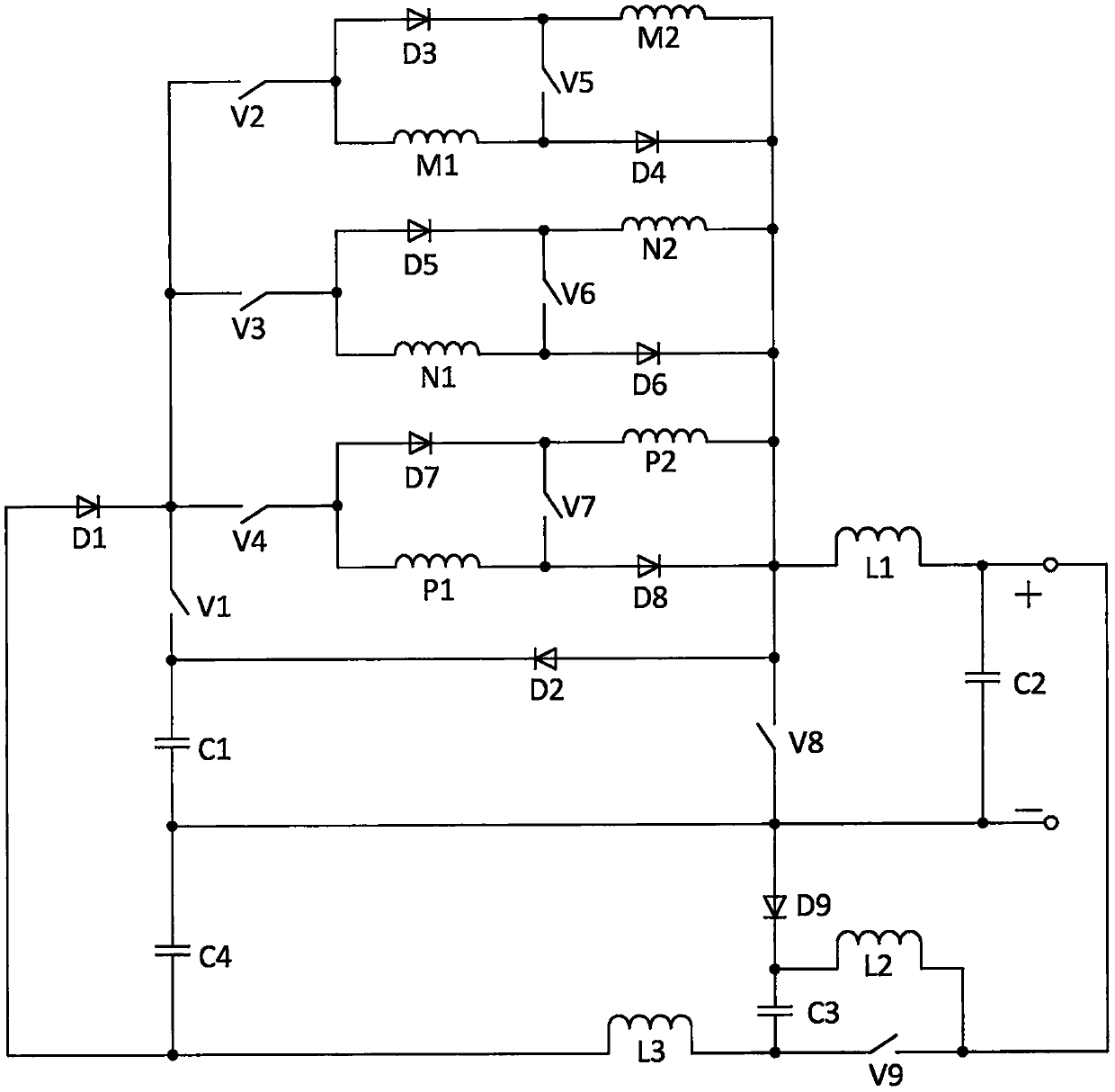
[0020] In this embodiment, the switched reluctance generator converter system with direct-boost voltage converter, generator voltage and excitation without isolation, the circuit structure of the converter system is as attached figure 1As shown, it consists of the first diode D1, the second diode D2, the third diode D3, the fourth diode D4, the fifth diode D5, the sixth diode D6, the seventh and second Diode D7, eighth diode D8, ninth diode D9, first switch V1, second switch V2, third switch V3, fourth switch V4, fifth switch V5, sixth Switching tube V6, seventh switching tube V7, eighth switching tube V8, ninth switching tube V9, the first branch winding M1 of the first phase winding, the second branch winding M2 of the first phase winding, the first branch winding of the second phase winding N1, the second phase winding, the second branch winding N2, the third phase winding, the first branch winding P1, the third phase winding, the second branch winding P2, the first capacit...


PUM


Abstract

A direct boost variable power generation voltage variable excitation non-isolated switch reluctance generator conversion system is formed by nine diodes, nine switch tubes, a three-phase winding, fourcapacitors, and three inductors. During each phase winding excitation and power generation operation, a power generation voltage value is naturally increased. Through a fifth switch tube (a first phase winding, other corresponding ones), continuously changing power generation voltages can be further obtained. Through a ninth switch tube which is the only switch tube, under the condition that an isolation link is not needed, continuously variable excitation voltages can be acquired and can directly participate in power generation output. Simultaneously, a storage battery is abandoned and an excitation design is reinforced. Based on that, a problem that a power generation voltage is continuously adjusted by the conversion system is solved, and an excitation voltage directly affects an output power generation voltage; controllability is enhanced; and with a simple structure and control, flexibility and adaptability of the system are greatly improved. The system is suitable for various low-power compact high-speed switch reluctance generator system fields.

Description

technical field [0001] The invention relates to the field of switched reluctance motor systems, in particular to a switched reluctance generator converter system and a control method thereof, which directly raise the generating voltage, the generating voltage is adjustable, the excitation voltage is adjustable, there is no isolation link and no battery common ground. Background technique [0002] Among the mainstream motors, the switched reluctance motor has the simplest and strongest structure, and has no winding on the rotor and guide bars to dissipate heat, so the cost should be the lowest, and it should have broad application prospects, including being used as a generator, compared with permanent magnet synchronous The cost of generators has been greatly reduced. However, the current research and application development on it is relatively slow. The key reason is that its converter system is immature and has not yet reached the level of large-scale finalized application. ...

Claims


Application Information

Patent Timeline
IPC IPC(8): H02P9/30H02P9/38
CPCH02P9/305H02P9/38
Inventor 孙冠群宋春伟王颖
Owner CHINA JILIANG UNIV
Why Eureka
Try Eureka