Dynamic battery power management

A power management system, battery technology, applied in the direction of battery continuous discharge, battery circuit device, different battery charging, etc., to achieve the effect of preventing device shutdown, enhancing user experience, and good device performance

Inactive Publication Date: 2019-11-19
GOOGLE LLC
View PDF7 Cites 0 Cited by
  • Summary
  • Abstract
  • Description
  • Claims
  • Application Information

AI Technical Summary

Problems solved by technology

Under certain conditions, the power management system may limit the current drawn from the battery to prevent the device from shutting down

Method used


Image

  • Dynamic battery power management
  • Dynamic battery power management
  • Dynamic battery power management

Examples


Embodiment Construction

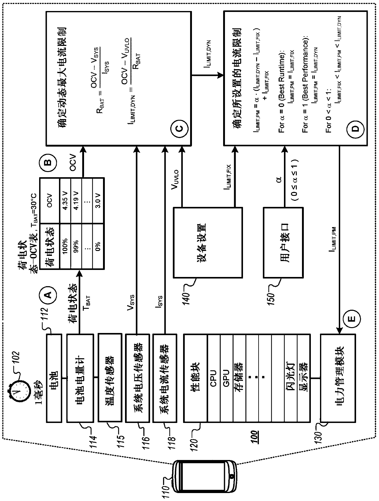
[0037] figure 1 is a diagram illustrating an example of a system 100 for dynamic battery power management. System 100 includes a battery powered device 110, and device 110 manages the rate at which it consumes power from the battery. figure 1 The example of shows how device 110 can adjust the current limit to take into account the current state of device 110 and its battery. figure 1 Stages (A) to (E) are shown, showing the data flow.

[0038] In some implementations, device 110 may dynamically adjust current limits and other power management settings in response to changing conditions. While device 110 is in use, the device-level current limit of device 110 may be adjusted to reflect changes in temperature, battery impedance, and battery condition. For example, a variable current limit can be set to account for changes in battery age, battery temperature, device temperature, battery state of charge, and other factors. As a result, device 110 may change its current limit i...


PUM


Abstract

Methods, systems, and devices, including machine-readable media, for dynamic battery power management are disclosed. In some implementations, an electronic device (110) that is powered by a battery (112) senses a voltage (via 116, during stage A) provided by the battery (112) and an electric current (via 118, during stage A) provided by the battery (112). The electronic device (110) determines a present state (via 114, during stage A) of the battery (112). The electronic device (110) determines a current limit (during stages C and D) for the electronic device (110) based on the sensed voltage(via 116, during stage A) and electric current (via 118, during stage A) and the determined present state (via 114, during stage A) of the battery (112). The electronic device (110) manages power use(via 130, during stage E) of the electronic device (110) to maintain electric current draw from the battery (112) at or below the electric current limit.

Description

Background technique [0001] Battery-powered electronic devices often implement power management systems to regulate battery power usage. Under certain conditions, the power management system may limit the current drawn from the battery to prevent the device from shutting down. Contents of the invention [0002] In some implementations, a battery-powered electronic device may determine a time-varying current limit to account for changing conditions, such as the state-of-charge of the battery, the age of the battery, and the temperature of the battery. Battery and system conditions can be sensed at repeated intervals and used to determine the dynamic maximum current limit. The dynamic maximum current limit may change over time as sensed battery and system conditions change. The device power management system may apply a dynamic maximum current limit or another dynamic current limit to allow for increased performance while still avoiding current levels that would cause the ba...

Claims


Application Information

Patent Timeline
Patent Type & Authority Applications(China)
IPC IPC(8): H02J7/00H04W52/02G01R31/389
CPCH04W52/0261G01R31/389Y02D30/70H02J7/007182H02J7/007192H02J7/00714H02J7/007194H02J7/0047H02J7/00H02J7/0025G01R31/36
Inventor 恩里克·罗梅罗·平塔多贾靓斯里坎斯·拉克石米坎萨艾克拉弗亚·辛格
Owner GOOGLE LLC
Why Eureka
Try Eureka