
Spiral flow self-desilting type desilting filter tank

A technology of self-discharging and sedimentation tank, applied in the direction of filtration loop, filtration separation, sedimentation tank, etc., can solve the problems of inability to meet the requirements of irrigation, poor sedimentation effect, and insufficient sedimentation, and achieve simple structure, Improve sand removal efficiency, low investment and operating costs

Active Publication Date: 2019-11-22
UNIV OF JINAN
View PDF9 Cites 2 Cited by
  • Summary
  • Abstract
  • Description
  • Claims
  • Application Information

AI Technical Summary

Problems solved by technology

[0003] In order to achieve this purpose, grit chambers are commonly used at present, but the effect of traditional grit chambers is not good, and the grit chambers are not thorough enough to meet the requirements of irrigation.
In addition, because the traditional desilting tank only depends on the natural desilting of sand in the process of water flow, the journey of desilting is long

Method used


Image

  • Spiral flow self-desilting type desilting filter tank
  • Spiral flow self-desilting type desilting filter tank
  • Spiral flow self-desilting type desilting filter tank

Examples


Embodiment 1

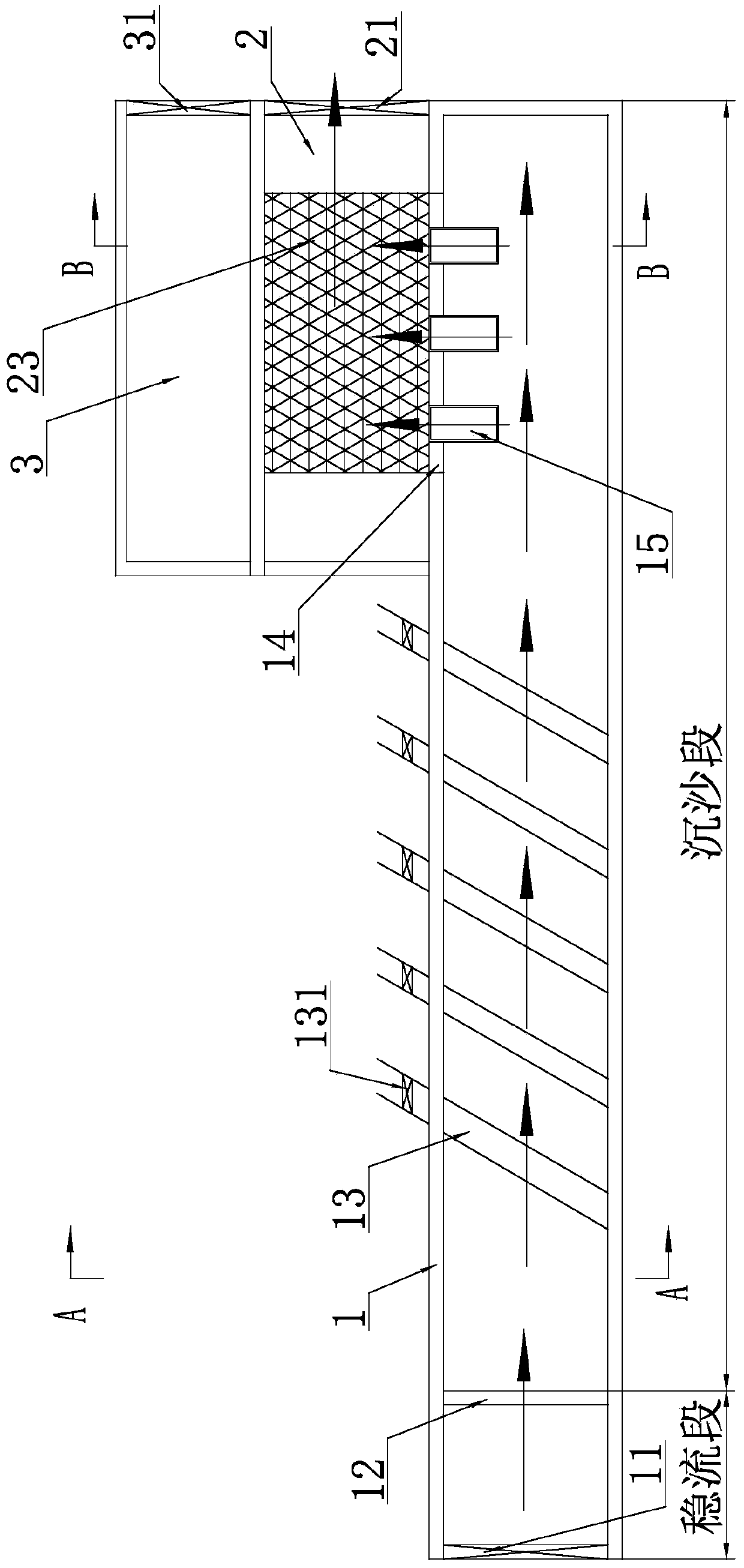
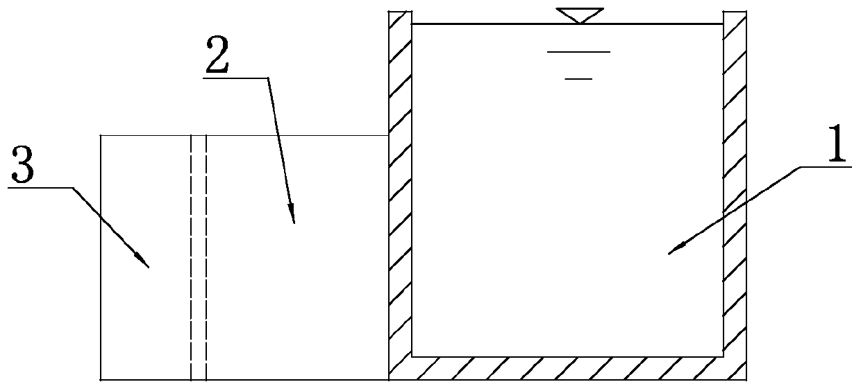
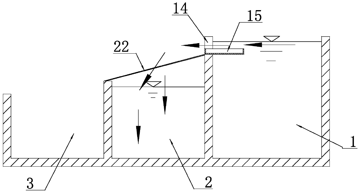
[0036] Such as figure 1 As shown, a spiral flow self-discharging sand filter tank includes a grit chamber 1, and the tail end of the grit chamber 1 is provided with a clear water pool 2, and the described grit chamber 1 and the clean water pool 2 jointly form a L-shaped structure, and if figure 2 As shown, the height of the clear water tank 2 is less than the height of the grit chamber 1. The front end of the grit chamber 1 is provided with a water inlet gate 11 , and the rear end of the clean water tank 2 is provided with a water outlet gate 21 . The wall between the grit chamber 1 and the clean water pond 2 is provided with a first gap 14, and the water in the grit chamber 1 overflows laterally into the clean water pond 2 through the first gap 14, And flow out through the outlet gate 21 of the clear water pool 2 for farmland irrigation.

[0037] Such as figure 1 As shown, the front end of the grit chamber 1 is provided with a regulating plate 12 , and the regulating pla...

Embodiment 2

[0057] Such as Figure 8 As shown, the sand discharge vortex 13 is perpendicular to the axis of the grit chamber 1, one end of the sand discharge vortex 13 extends to the outside of the grit chamber 1, and the sand discharge vortex 13 One end extending to the outside of the grit chamber 1 is provided with a sand discharge valve 131, and the height of the end with the sand discharge valve 131 is lower than that of the other end, and the rest of the structure is the same as that of the first embodiment.


PUM


Abstract

The invention discloses a spiral flow self-desilting type desilting filter tank, and relates to the technical field of agricultural irrigation. The desilting filter tank comprises a desilting basin, aclean water basin is arranged at the tail end of the desilting basin, a water inlet gate is arranged at the front end of the desilting basin, a water outlet gate is arranged at the rear end of the clean water basin, a first notch is formed in a wall body between the desilting basin and the clean water basin, and a plurality of overflow grooves are formed in the bottom surface of the first notch.A flow regulating plate in the desilting basin divides the internal space of the desilting basin into a flow stabilizing section and a desilting section. At least two desilting scrolls are arranged atthe bottom of the desilting section, one end of each desilting scroll penetrates through the side wall of the desilting basin and extends out of the desilting basin, and a second notch is formed in the desilting scroll located in the desilting basin. The desilting filter tank can achieve the dual effects of desilting and filtering within the shortest effective length, the desilting efficiency isgreatly improved, and the requirement that surface water enters ditches and canals for irrigation is met.

Description

technical field [0001] The invention relates to the technical field of agricultural irrigation, in particular to a spiral flow self-discharging sand filter pond. Background technique [0002] At present, the problems of water shortage and water pollution in our country are becoming more and more serious, and it is an inevitable trend to carry out extensive research on water-saving irrigation agriculture. Most of the water sources used in water-saving irrigation technology are surface water, but most of the surface water has a high sediment content. If the surface water is directly used in the irrigation system, it will inevitably cause blockage of pipelines and other facilities, which is not conducive to Agricultural irrigation. Therefore, water-saving irrigation technology requires water sources with very little sand content, so it is necessary to purify the sand in the surface water before irrigation. [0003] In order to achieve this purpose, grit chambers are commonly ...

Claims


Application Information

Patent Timeline
Patent Type & Authority Applications(China)
IPC IPC(8): B01D36/04B01D21/02B01D21/24
CPCB01D21/02B01D21/245B01D36/04
Inventor 李旺林霍云李玉喜
Owner UNIV OF JINAN
Learn More