A Coating Guide Floating Mechanism Used in Overhead Bare Wire Coating Device

A technology of coating device and floating mechanism, applied in overhead line/cable equipment, device for coating liquid on the surface, coating, etc., can solve the problem of failing to meet the requirements of coating technology and insulating electrical performance indicators, and unable to guarantee the thickness of insulating materials. Uniformity, inability to maintain vertical relationship, etc., to eliminate adverse effects, prevent reverse leakage, and reduce moving resistance

Active Publication Date: 2021-05-28
SHANGHAI MUNICIPAL ELECTRIC POWER CO
View PDF10 Cites 0 Cited by
  • Summary
  • Abstract
  • Description
  • Claims
  • Application Information

AI Technical Summary

Problems solved by technology

[0008] In actual use, such as figure 2 As shown in , due to the rigid connections (commonly known as hard connections) between the various components of the entire machine, and the machine itself has a certain self-weight, when the machine is actually coating, the longitudinal centerline of the overhead wire There will be a certain angle between x' and the longitudinal centerline x of the coating assembly outlet of the coating machine, that is, the longitudinal centerline of the overhead wire and the longitudinal centerline of the coating assembly outlet are not parallel or coincident, resulting in The plane y where the coating component outlet of the coating machine is located and the longitudinal centerline x' of the overhead conductor cannot maintain a complete vertical relationship, so the thickness uniformity of the insulating material coated on the entire overhead conductor cannot be guaranteed (due to the machine Due to the self-weight of the insulation material, the coating thickness of the insulating material will basically be thin at the top and thick at the bottom), so that the corresponding coating technical requirements and insulation electrical performance indicators cannot be met.

Method used


Image

  • A Coating Guide Floating Mechanism Used in Overhead Bare Wire Coating Device
  • A Coating Guide Floating Mechanism Used in Overhead Bare Wire Coating Device
  • A Coating Guide Floating Mechanism Used in Overhead Bare Wire Coating Device

Examples


Embodiment Construction

[0039] The present invention will be further described below in conjunction with the accompanying drawings and embodiments.

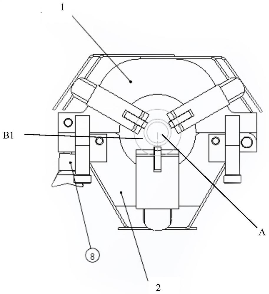
[0040] image 3 neutralize Figure 4 Among them, the technical solution of the present invention provides a coating guiding floating mechanism for an overhead bare wire coating device, and its invention points are:

[0041] A ring-shaped guiding floating mechanism composed of an upper pressing part 1 and a lower pressing part 2 is provided;

[0042] One end of the upper pressing piece and the lower pressing piece are hinged, and the other end is buckled through the movable connecting plate 8 to form a snap-fit ​​ring structure in which the overhead wire to be coated can be clamped penetratingly.

[0043] Obviously, the diameter of the inner circle of the snap-fit ​​ring structure must be greater than the diameter of the wire outlet of the coating assembly in the coating device.

[0044] On one side of the snap-fit ​​ring structure, a rigid centering co...


PUM


Abstract

The utility model relates to a coating guide floating mechanism used for an overhead bare wire coating device, which belongs to the coating field. It includes a fastening ring structure composed of an upper pressing piece and a lower pressing piece; on one side of the ring structure, a centering component that can move along the outer surface of the overhead wire is arranged to hold the bare overhead wire to be coated and the coated wire. The centering position relationship between the wire outlets of the coating assembly; the hook assembly is set on the same side of the ring structure to establish an elastic connection relationship with the frame of the coating device; the other side of the ring structure is connected to the coating device The coating components in are fixedly connected to form a rigid connection relationship. It ensures that the thickness of the insulating material coating layer coated on the entire outer surface of the overhead wire is uniform by forcing the center of the outlet of the coating component to always coincide with the longitudinal centerline of the overhead wire; eliminating the impact of wire bending deformation on the thickness of the coating layer coming adverse effects. It can be widely used in the fields of transformation and operation management of overhead transmission lines.

Description

technical field [0001] The invention belongs to the field of coating, and in particular relates to a coating guiding device used for an overhead bare wire coating device. Background technique [0002] Overhead transmission lines (also known as overhead wires or overhead lines) are the main way of power transmission. [0003] Due to the large range of transmission lines, the distribution points are wide, the geographical environment is complex, the natural environment is harsh, and the power transmission lines, poles and towers and accessories are exposed to the wild for a long time, often due to external forces, tree branches, high-altitude objects and other objects that may encounter overhead lines Objects close to the transmission wires will adversely affect the safety and efficient power supply; in addition, among the accidents reported by the State Grid every year, the accidents caused by low-voltage electric shock account for the vast majority. [0004] At present, var...

Claims


Application Information

Patent Timeline
Patent Type & Authority Patents(China)
IPC IPC(8): B05C5/02B05C11/00H01B13/16H02G1/02
CPCB05C5/0241B05C11/00H01B13/16H02G1/02
Inventor 王昭夏厉优栋莫颖涛席严
Owner SHANGHAI MUNICIPAL ELECTRIC POWER CO
Why Eureka
Try Eureka