
Special-shaped part feeding and shaping mechanism

A technology of special-shaped parts and driving mechanism, which is applied in metal processing and other directions, can solve problems such as difficult clamping, prone to tilting at both ends, and incorrect posture, and achieve the effect of coordinated and unified feeding work, simple and compact structure, and ingenious conception

Pending Publication Date: 2019-11-22
宁波久荣液压器材有限公司
View PDF1 Cites 1 Cited by
  • Summary
  • Abstract
  • Description
  • Claims
  • Application Information

AI Technical Summary

Problems solved by technology

[0004] However, this kind of equipment can usually only be applied to shaft parts with specified shapes, and for special-shaped shaft parts with different shaft diameters, due to the inconsistent center of gravity of different parts, when it is located above the saw teeth, the two ends are prone to tilt , so that the special-shaped parts are stuck in a certain position and cannot be fed forward. Even if the special-shaped parts are sent to the predetermined position, it will be difficult to clamp because of the incorrect posture, that is, this equipment cannot be applied to special-shaped parts with different shaft diameters.

Method used


Image

  • Special-shaped part feeding and shaping mechanism
  • Special-shaped part feeding and shaping mechanism
  • Special-shaped part feeding and shaping mechanism

Examples


Embodiment Construction

[0042]The following are specific embodiments of the present invention and in conjunction with the accompanying drawings, the technical solutions of the present invention are further described, but the present invention is not limited to these embodiments.

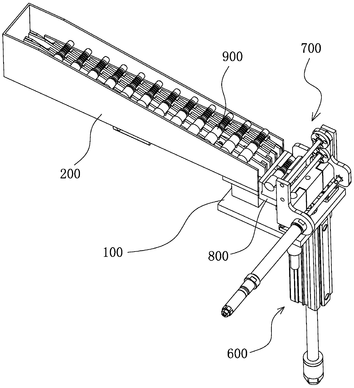
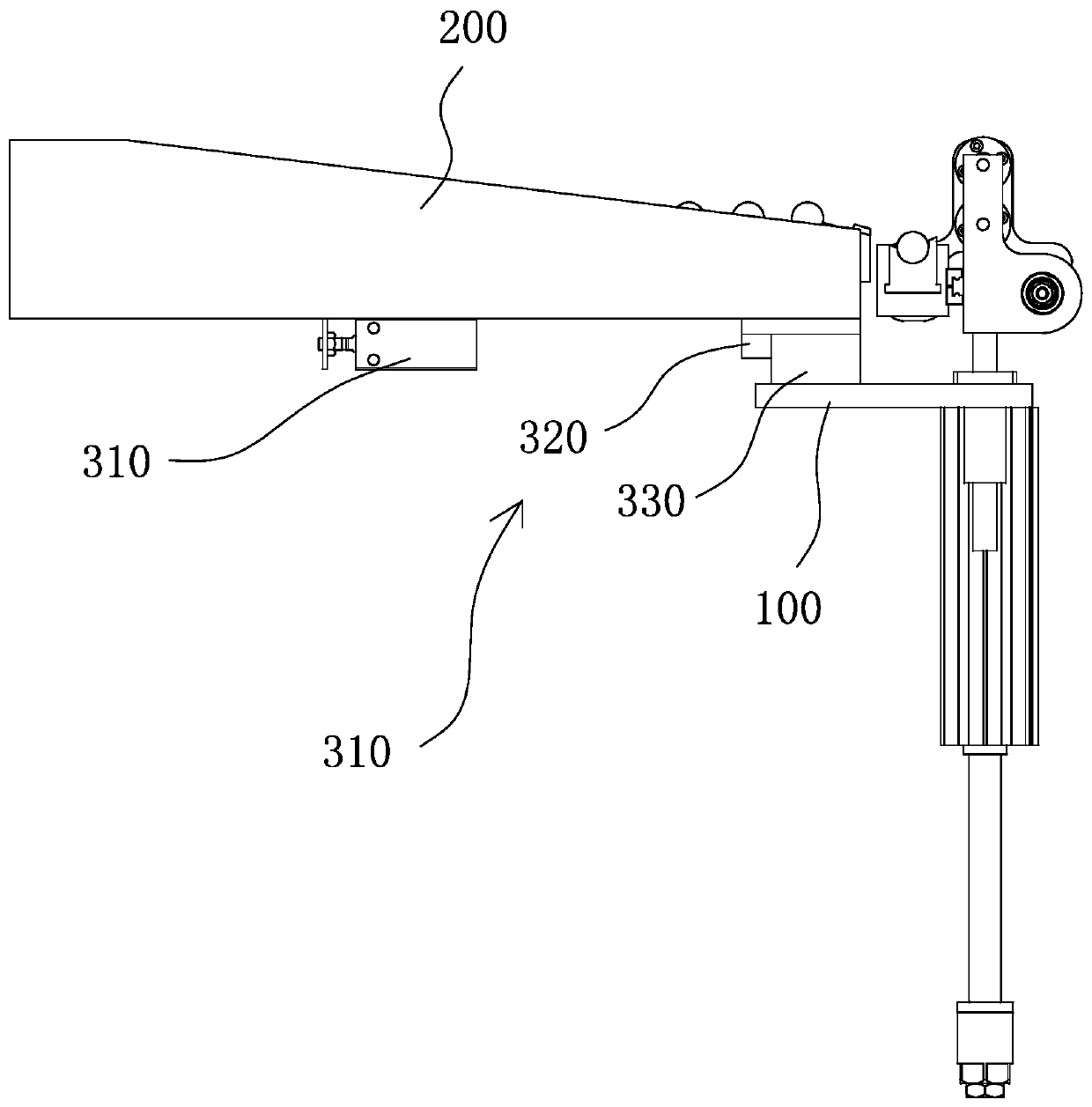
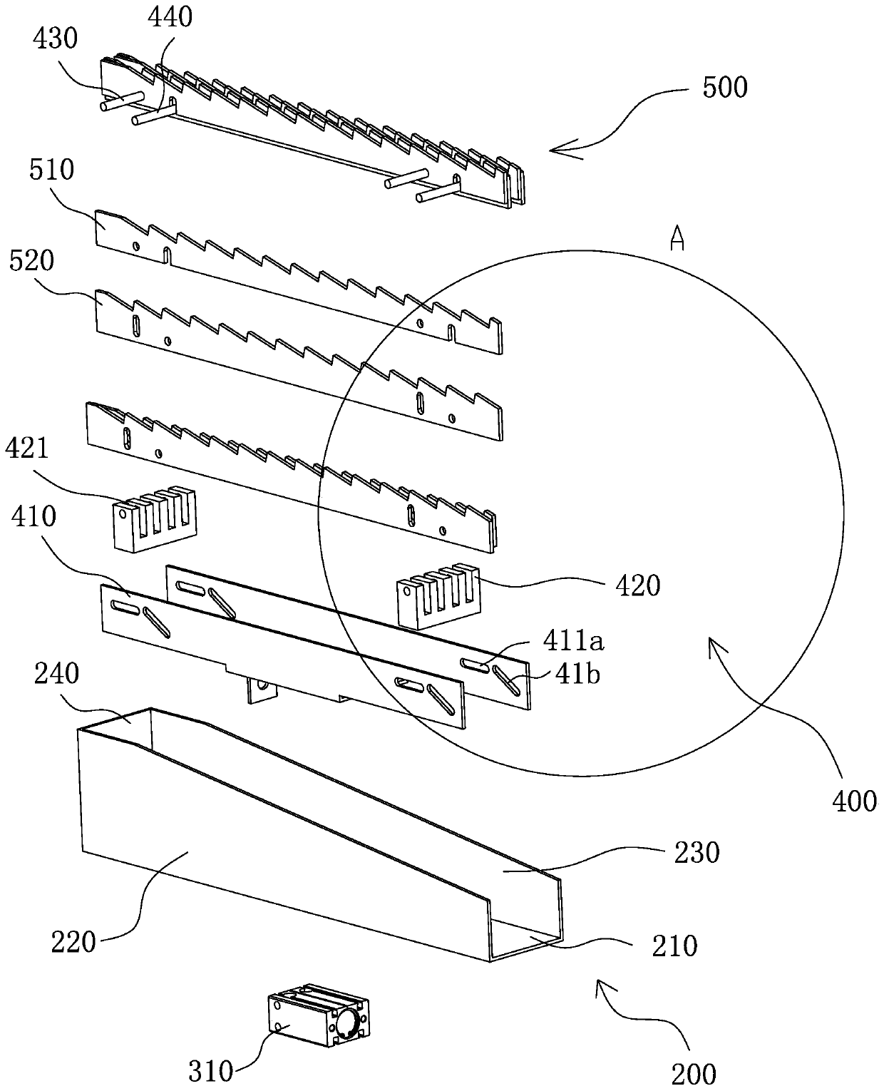
[0043] Such as Figure 1 to Figure 10 As shown, the feeding and shaping mechanism for special-shaped parts includes a support plate 100, a feeding hopper 200, a driving mechanism 300, a linkage assembly 400, several sawtooth feeding assemblies 500, a material receiving assembly 800, a lifting assembly 600, and a translation assembly 700.

[0044] The sawtooth feeding assembly 500 includes a fixed rack 510 and a movable rack 520, the upper ends of the fixed rack 510 and the movable rack 520 are respectively arranged with several first helical teeth 511, several second helical teeth 521, the first helical teeth 511 and the second helical tooth 521 have the same tooth profile and are set low at the front and high at the back. ...


PUM


Abstract

The invention provides a special-shaped part feeding and shaping mechanism, and belongs to the technical field of automatic feeding. The mechanism comprises saw tooth feeding assemblies, a linkage assembly and a driving mechanism, wherein the saw tooth feeding assemblies comprises fixed racks and movable racks, a plurality of first helical teeth and a plurality of second helical teeth are arrangedat the upper ends of the fixed racks and the movable racks respectively, the first helical teeth and the second helical teeth are arranged in a staggered manner, the plurality of saw tooth feeding assemblies are arranged in parallel, height differences corresponding to the workpiece profile are arranged between the plurality of saw tooth feeding assemblies, the linkage assembly is used for connecting all movable racks in series, and the driving mechanism is connected with the linkage assembly and is used for driving all the movable racks to synchronously move up and down relative to the fixedracks. The mechanism has the advantages of being reliable in work.

Description

technical field [0001] The invention belongs to the technical field of automatic feeding equipment, and relates to a feeding and shaping mechanism for special-shaped parts. Background technique [0002] With the continuous increase of labor costs, the demand for industrial automation in manufacturing enterprises is becoming more and more urgent. In order to improve production efficiency and reduce costs, a large number of enterprises have transformed the original CNC machine tools through automation to realize automatic loading and unloading. [0003] For example, a Chinese patent with an application number of 201620746624.2 discloses a feeding structure applied to processing shafts, including a frame, and the frame is provided with a fixed sawtooth plate and a movable sawtooth plate that can move up and down. There are sawtooth distributed on the fixed sawtooth plate and the movable sawtooth plate, wherein the sawtooth of the fixed sawtooth plate and the sawtooth of the mo...

Claims


Application Information

Patent Timeline
Patent Type & Authority Applications(China)
IPC IPC(8): B23Q7/00
CPCB23Q7/00
Inventor 王慧
Owner 宁波久荣液压器材有限公司
Learn More