Two-rotating two-moving parallel machining swing head mechanism

A swing head and parallel technology, applied in the field of mechanical processing, can solve the problems of large space occupied by the drive rod, poor motion state, and singularity of the layout form, etc., and achieve the effect of compact structure, good dynamic performance, and solving singularity problems

Active Publication Date: 2019-11-22
YANSHAN UNIV
View PDF10 Cites 1 Cited by
  • Summary
  • Abstract
  • Description
  • Claims
  • Application Information

AI Technical Summary

Problems solved by technology

The patent document with the application number 201010507587.7 discloses a space four-degree-of-freedom parallel mechanism and a spraying robot, in which the spraying operation mechanism is a four-branch parallel mechanism, and the four linear drive branches directly drive the moving platform, and the swing of the drive rod takes up a large space. It is not suitable as a mechanism for parallel processing heads, and there are singularity problems in the layout of the mechanism, and the motion state is not good

Method used


Image

  • Two-rotating two-moving parallel machining swing head mechanism
  • Two-rotating two-moving parallel machining swing head mechanism
  • Two-rotating two-moving parallel machining swing head mechanism

Examples


Embodiment 1

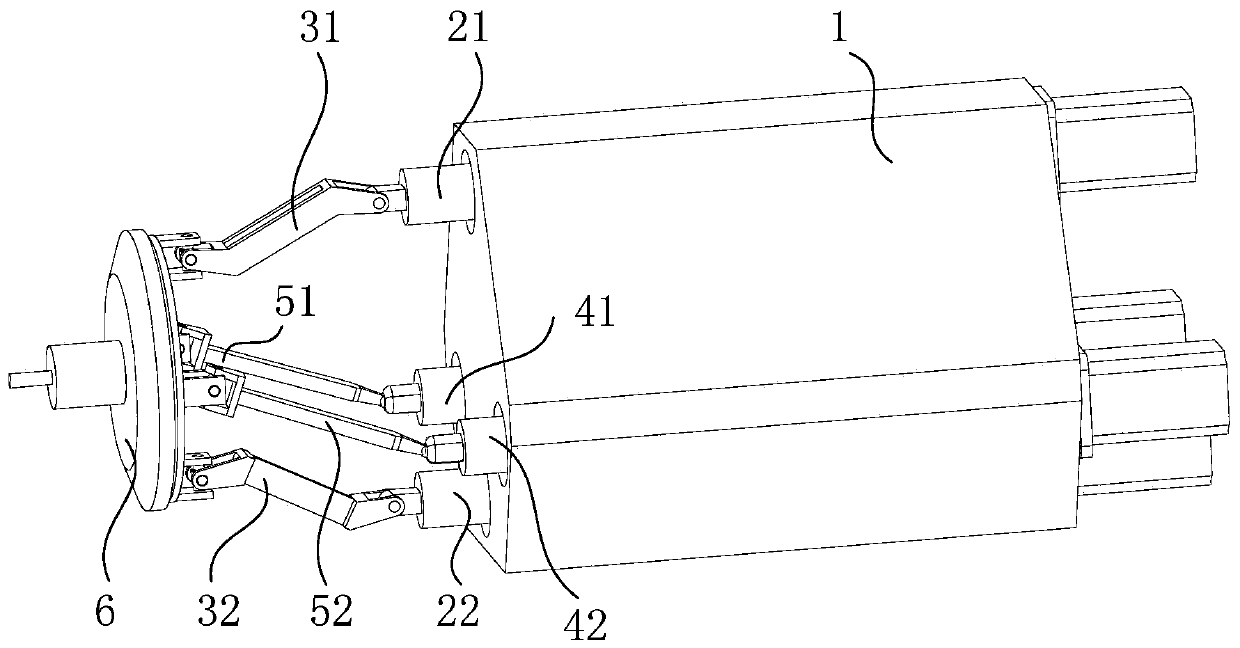
[0037] exist figure 2 In the schematic diagram of the two-rotation and two-movement parallel processing swing head mechanism shown, four sets of linear drive modules 21, 22, 41, 42 are fixed on the fixed cylinder 1, wherein the second linear drive module 21 and the first linear drive module 22 are fixed In the left and right symmetry plane of the fixed cylinder 1, two sets of third linear drive modules 41 and 42 are symmetrically fixed on both sides of the left and right symmetry plane, and the two sets of third linear drive modules 41 and 42 are arranged close to the second linear drive module 21, and the first The linear drive module 22 and two groups of third linear drive modules 41, 42 pass through the moving end of the second linear drive module 21, and the first ends of the two first connecting rods 31, 32 are respectively connected to the second linear drive module through a rotating hinge. The module 21 is connected to the moving end of the first linear drive module 2...

Embodiment 2

[0039] image 3It is a structural schematic diagram of the two-rotation and two-movement parallel processing swing head mechanism according to the second embodiment of the present invention, wherein four sets of linear drive modules 21, 22, 41, 42 are fixed on the fixed cylinder 1, and the first linear drive module 22 and the second linear drive module 21' are fixed in the left and right symmetrical planes of the fixed cylinder 1, and two sets of third linear drive modules 41, 42 are symmetrically fixed on both sides of the left and right symmetrical planes of the fixed cylinder 1; the two first connecting rods 31, 32 The first ends are respectively connected to the moving ends of the two groups of first linear drive modules through rotating hinges, and the first ends of the two second connecting rods 51, 52 are respectively connected to the two groups of third linear drive modules 41, 42 through spherical hinges. The moving end is connected; the second end of each first conne...

Embodiment 3

[0043] exist Figure 4 In the shown schematic diagram of the two-rotation and two-movement parallel processing swing head mechanism according to the third embodiment of the present invention, four sets of linear drive modules 21, 22, 41, 42 are fixed on the fixed cylinder 1, and the first linear drive module 21 and the second linear drive module 22 are fixed in the left and right symmetrical planes of the fixed cylinder 1, and two groups of third linear drive modules 41, 42 are symmetrically fixed on both sides of the left and right symmetrical planes of the fixed cylinder; the first of the two first connecting rods 31, 32 The two ends are respectively connected to the moving ends of the first linear drive module 22 and the second linear drive module 21 through rotating hinges, and the first ends of the two second connecting rods 51, 52 are respectively connected to the two groups of third linear drive modules through ball joints. The moving ends of 41 and 42 are connected; th...


PUM


Abstract

The invention discloses a two-rotating two-moving parallel machining swing head mechanism. The two-rotating two-moving parallel machining swing head mechanism comprises a fixed barrel, four linear driving modules, four connecting rod branches and a movable platform with a machining spindle. The four linear driving modules are fixed to the fixed barrel, the first linear driving module and the second linear driving module are fixed into the left-right symmetric faces of the fixed barrel, and the two third linear driving modules are fixed to the two sides of the left-right symmetric faces of thefixed barrel. Stretching barrels of the second linear driving module and the third linear driving modules are identical in structure and penetrate through a stretching barrel of the first linear driving module. One ends of two first connecting rod branches are connected with the movable ends of the first linear driving module and the second linear driving module through rotating hinges correspondingly. One ends of two second connecting rod branches are connected with the movable ends of the two third linear driving modules through spherical hinges correspondingly. The other ends of the connecting rod branches are connected with the movable platform through universal hinges. The two-rotating two-moving parallel machining swing head mechanism is good in dynamic property, high in rigidity andhigh in machining precision, and curved face machining is achieved.

Description

technical field [0001] The invention relates to the field of mechanical processing, in particular to a two-rotation and two-movement parallel processing swing head mechanism. Background technique [0002] Compared with the series mechanism, the parallel processing head has the advantages of high rigidity, high precision, and many degrees of freedom. It can realize curved surface processing in the field of mechanical processing and effectively improve the processing accuracy. and other industries have important influence. [0003] At present, most parallel processing heads are three-degree-of-freedom parallel mechanisms, such as the Z3 spindle head. In the prior art, the patent document with application number 200910228104.7 discloses a parallel mechanism that can realize two-dimensional translation and two-dimensional rotation, which includes a fixed frame, a moving platform and four branch chain structures. The branch chain structure in the present invention It is general...

Claims


Application Information

Patent Timeline
IPC IPC(8): B25J9/00
CPCB25J9/0063
Inventor 赵铁石田昕吴振魁
Owner YANSHAN UNIV
Why Eureka
Try Eureka