
Rotary mechanical hand for machining

A mechanical processing and rotary technology, applied in the field of manipulators, can solve problems affecting life and cost control, short life of pressure sensors, and installation errors of grippers, etc., to improve gripping ability and gripping stability, and improve gripping efficiency , the effect of improving the accuracy

Active Publication Date: 2019-11-22
GUILIN UNIV OF AEROSPACE TECH
View PDF8 Cites 3 Cited by
  • Summary
  • Abstract
  • Description
  • Claims
  • Application Information

AI Technical Summary

Problems solved by technology

[0002] In mechanical processing, some large-volume parts need to be transported by multiple people to install, which is not only time-consuming and labor-intensive, but also has potential safety hazards. Therefore, manipulators are usually used to grab parts and play a supporting role.
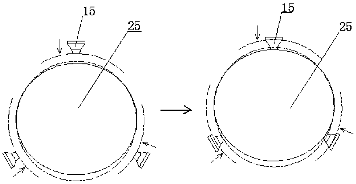
[0003] The current manipulators, such as three-jaw or four-jaw manipulators, when grasping the workpiece, it is difficult to ensure that each jaw can grasp the workpiece with roughly the same force at the same time, such as elliptical workpieces or irregular Workpieces, etc., even cylindrical workpieces such as figure 1 As shown, due to the machining error and the installation error of the jaws, it is difficult to ensure that each jaw is evenly clamped
In this regard, although it is possible to detect and control the gripping force of each jaw by setting a pressure sensor, this structural form is subject to greater friction and extrusion force between the pressure sensor and the workpiece at all times, resulting in a longer service life of the pressure sensor. Very short, the pressure sensor needs to be replaced frequently, affecting life and cost control

Method used


Image

  • Rotary mechanical hand for machining
  • Rotary mechanical hand for machining
  • Rotary mechanical hand for machining

Examples


Embodiment Construction

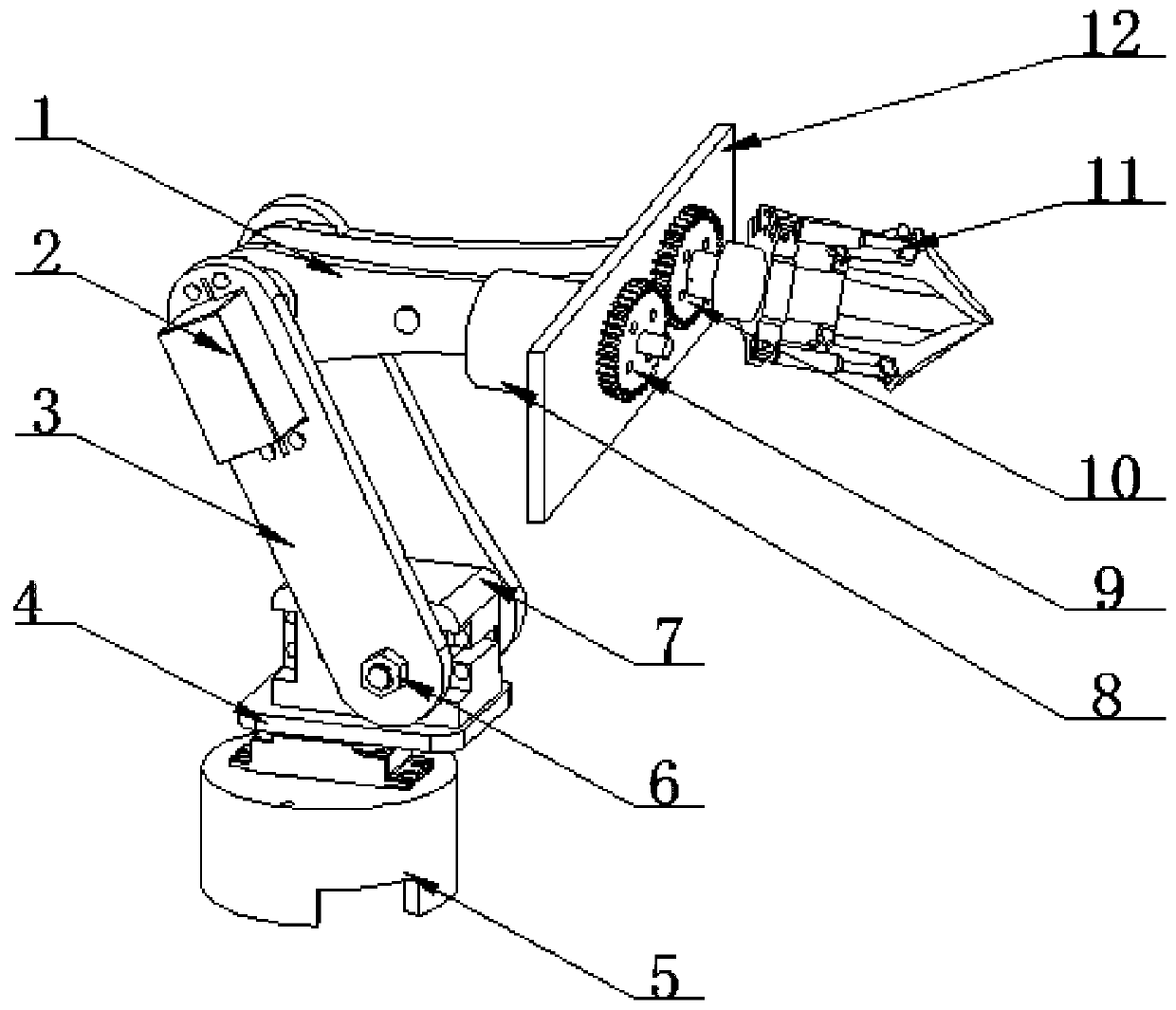
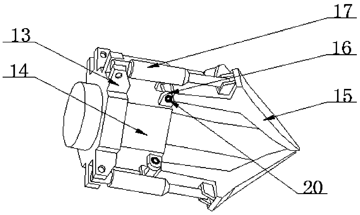
[0030] see Figure 2-5 , in an embodiment of the present invention, a rotary manipulator for mechanical processing, including a mechanical arm mechanism and a grasping mechanical claw 11, wherein three sets of circular arrays of the grasping mechanical claws 11 are installed and connected to the connecting plate 12 , the connecting plate is fixedly installed on the output end of the mechanical arm mechanism; each group of grabbing mechanical claws 11 is driven by a separate cylinder 17, so that the clamping jaws 15 of each grabbing mechanical claw 11 can be realized by the cylinder. action; it is characterized in that an angle detection assembly 20 is provided at the hinge of the end of the clamping jaw away from the clamping end, and the angle detection assembly 20 can detect the rotation angle of the clamping jaw at all times; A controller connected to the detection assembly 20, the controller independently controls each cylinder;

[0031] When grabbing the workpiece 25, th...


PUM


Abstract

The invention relates to the field of mechanical hands, in particular to a rotary mechanical hand for machining. Pressure sensors can be prevented from being adopted, and the problem is solved that pressure sensors at grabbing positions are damaged under great friction, collision and extrusion; when an angle detecting assembly detects the actions of a control cylinder at some time and the rotatingangle of the angle detecting assembly during detecting is smaller than a set threshold, a controller controls the cylinder to stop actions or continue to inject set gas into a cylinder body of the cylinder and then stop actions, required clamping force is kept, it is ensured that all claws can make contact with and clamp a workpiece, the grabbing capacity and grabbing stability of the mechanicalhand are effectively improved, and the grabbing precision is improved; the control mode is simple, it can be ensured that all the claws grab the workpiece with the force as identically or similarly aspossible, it is ensured that all the claws can make contact with and clamp the workpiece, the workpiece grabbing efficiency is improved, and the stress uniformity of al the claws can be ensured.

Description

technical field [0001] The invention relates to the field of manipulators, in particular to a rotary manipulator for machining. Background technique [0002] In mechanical processing, some large-volume parts need to be transported by multiple people to install, which is not only time-consuming and labor-intensive, but also has potential safety hazards. Therefore, manipulators are usually used to grab parts and play a supporting role. [0003] The current manipulators, such as three-jaw or four-jaw manipulators, when grasping the workpiece, it is difficult to ensure that each jaw can grasp the workpiece with roughly the same force at the same time, such as elliptical workpieces or irregular Workpieces, etc., even cylindrical workpieces such as figure 1 As shown, due to the machining error and the installation error of the jaws, it is difficult to ensure that each jaw is evenly clamped. In this regard, although it is possible to detect and control the gripping force of each ...

Claims


Application Information

Patent Timeline
Patent Type & Authority Applications(China)
IPC IPC(8): B25J15/10B25J19/00B25J11/00
CPCB25J11/00B25J15/10B25J19/00
Inventor 赵宏旺刘晓刚林德民
Owner GUILIN UNIV OF AEROSPACE TECH
Learn More