
Miniature steel pipe pile earth pressure and displacement monitoring device

A displacement monitoring and steel pipe pile technology, which is used in construction, infrastructure testing, infrastructure engineering, etc., can solve the problems of idle acquisition ports, many manpower to adjust the direction, and high cost, and achieves simple and convenient operation and measurement accuracy. And the effect of high survival rate and simple device structure

Pending Publication Date: 2019-11-22
QINGDAO TECHNOLOGICAL UNIVERSITY
View PDF0 Cites 2 Cited by
  • Summary
  • Abstract
  • Description
  • Claims
  • Application Information

AI Technical Summary

Problems solved by technology

At present, the soil pressure detection of micro-steel pipe piles is mostly applied by pasting strain gauges on the pile body, but it is easy to be affected by moisture, the survival rate is low, and the sealant cannot have air bubbles. The equipment for monitoring the displacement of micro-steel pipe piles or Most of the methods use inclinometer tubes. In order to successfully install the inclinometer tubes in place, it generally needs to be deeper than the installation depth. It is more troublesome to adjust the direction, requiring more manpower and high cost. When the output port transmits data, the acquisition port must be free.

Method used


Image

  • Miniature steel pipe pile earth pressure and displacement monitoring device
  • Miniature steel pipe pile earth pressure and displacement monitoring device
  • Miniature steel pipe pile earth pressure and displacement monitoring device

Examples


Embodiment

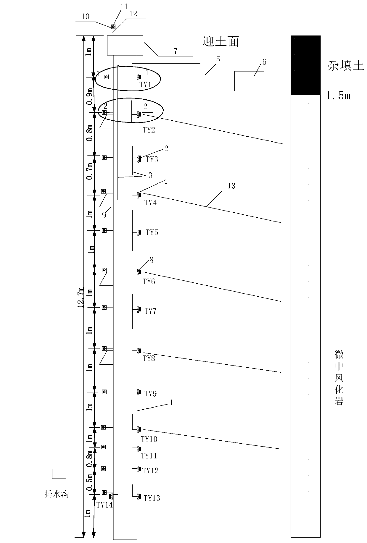
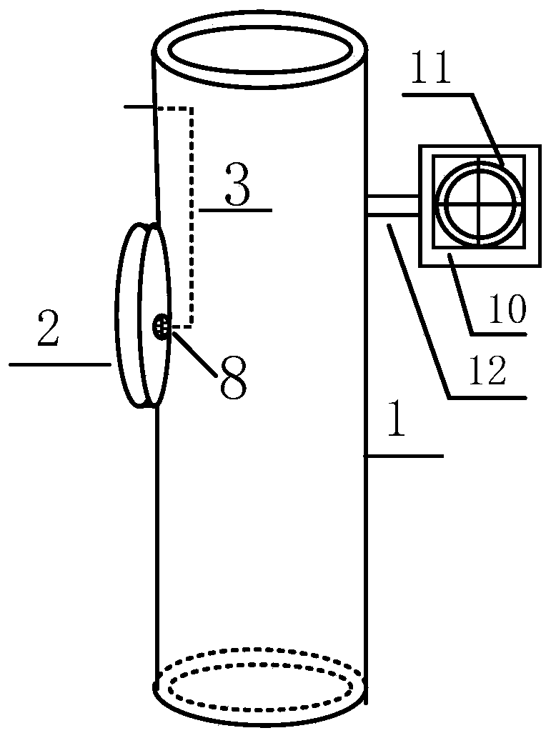
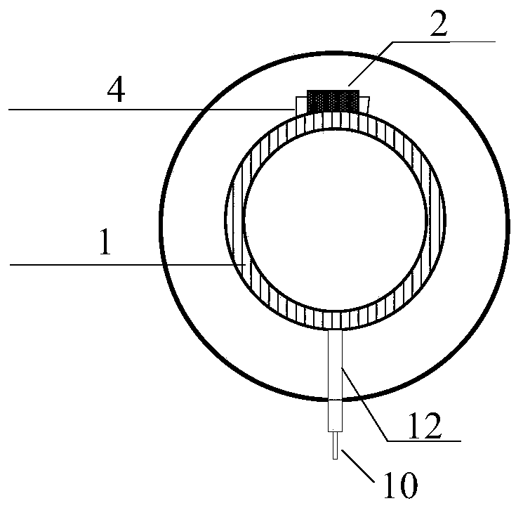
[0023] The main structure of the micro-steel pipe pile body resistive earth pressure gauge layout device described in this embodiment includes a micro-steel pipe pile 1, an XY-TY02A resistive micro-earth pressure gauge 2, a transmission line 3, a sensor metal protective shell 4, and a resistance tester. Strain gauge 5, data storage computer 6, crown beam 7, sensor mounting hole 8, waist beam 9, reflective sheet end support plate 10, reflective sheet 11, reflective sheet base steel head reinforcement 12; micro steel pipe pile 1 adopts diameter 127mm, For a seamless steel pipe with a thickness of 5 mm and a length of 12.7 meters, the sensor installation hole 8 is a round hole with a diameter of 5 mm formed in the micro steel pipe pile 1 by flame cutting, and the vertical symmetry axis of the round hole is vertically aligned along the micro steel pipe pile 1 , the centroid of the cross-section of the sensor installation hole 8 coincides with the centroid of the stressed membrane sid...


PUM

PropertyMeasurementUnit
The inside diameter ofaaaaaaaaaa
Lengthaaaaaaaaaa
Wall thicknessaaaaaaaaaa

Abstract

The invention belongs to the technical field of pile foundation engineering field test, and relates to a miniature steel pipe pile earth pressure and displacement monitoring device. A preset positionoutside a pile body is subjected to hole drilling and be welded to a sensor metal protective shell with the thickness slightly lower than an XY-TY02A resistance-type miniature earth pressure gauge, the pile body is pasted with the XY-TY02A resistance-type miniature earth pressure gauge, a transmission line of the XY-TY02A resistance-type miniature earth pressure gauge is introduced out of the inner part of a steel pipe pile through a sensor mounting hole to communicate with a data collecting system, and a preset position of the miniature steel pipe pile is subjected to reflector base welding and reflector pasting to achieved monitoring of displacement. According to the miniature steel pipe pile earth pressure and displacement monitoring device, the structure of the device is simple, operation is easy and convenient, reliability and stability are achieved, the measuring accuracy and the survival rate are high, the cost is low, manpower, material resources and time are saved, earth pressure change of a miniature steel pipe pile support of a rock soil foundation pit can be monitored in real time, test data are provided for miniature steel pipe pile support theory monitoring the rock soil foundation in site, and reference value is provided for engineering practice.

Description

Technical field: [0001] The invention belongs to the field test technology field of pile foundation engineering, and relates to a micro-steel pipe pile soil pressure and displacement monitoring device, which simultaneously measures the soil pressure of the micro-steel pipe pile and the displacement under the action of water and soil pressure. and actual engineering to provide reference value. Background technique: [0002] Miniature steel pipe piles generally refer to cast-in-place piles with a pile diameter of 100-300mm and a length-to-diameter ratio greater than 30, which adopt the construction technology of drilling strong reinforcement and pressure grouting. Only light construction machines are needed during construction, flexible pile layout, fast construction speed, strong adaptability to the construction site, and small impact on the environment. Therefore, micro-steel pipe piles with soil nails, advanced micro-pile composite soil nail support of anchor rods, micro-p...

Claims


Application Information

Patent Timeline
IPC IPC(8): E02D33/00
CPCE02D33/00E02D2600/10
Inventor 白晓宇张明义王永洪孙绍霞
Owner QINGDAO TECHNOLOGICAL UNIVERSITY
Learn More