Shaped tempering die for building
A technology for building and chemical steel, which is applied in the fields of building, building structure, and on-site preparation of building components, can solve the problems of affecting the molding effect of stairs, time-consuming, inconvenient construction, etc.
- Summary
- Abstract
- Description
- Claims
- Application Information
AI Technical Summary
Problems solved by technology
Method used
Image

Examples
no. 1 example
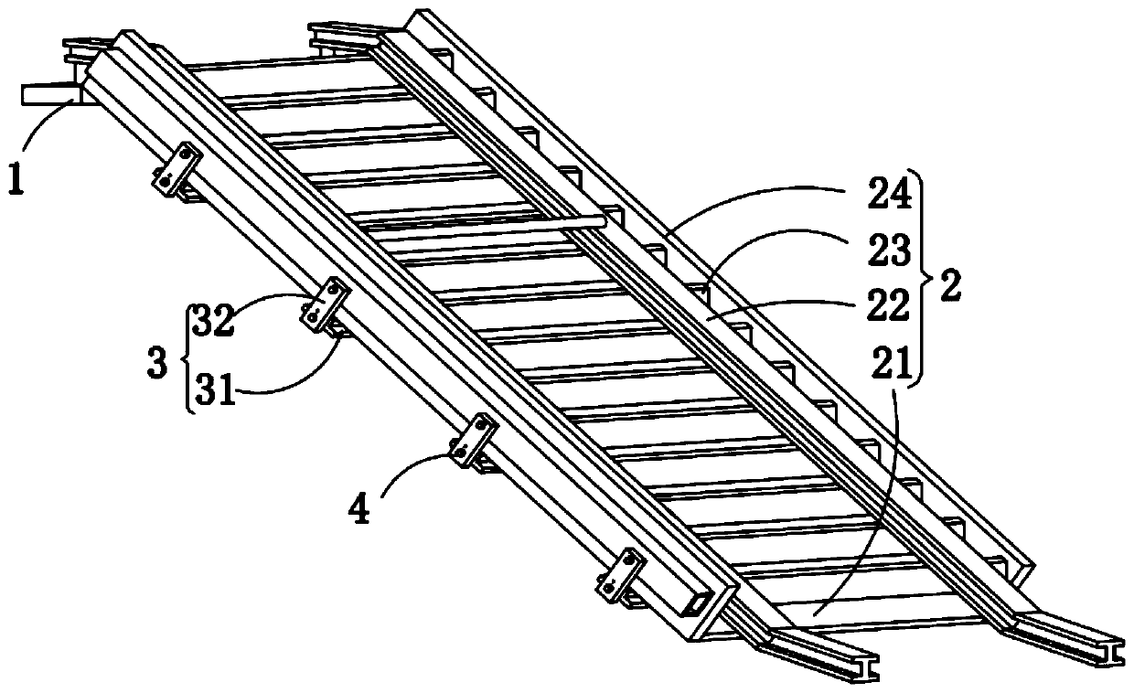
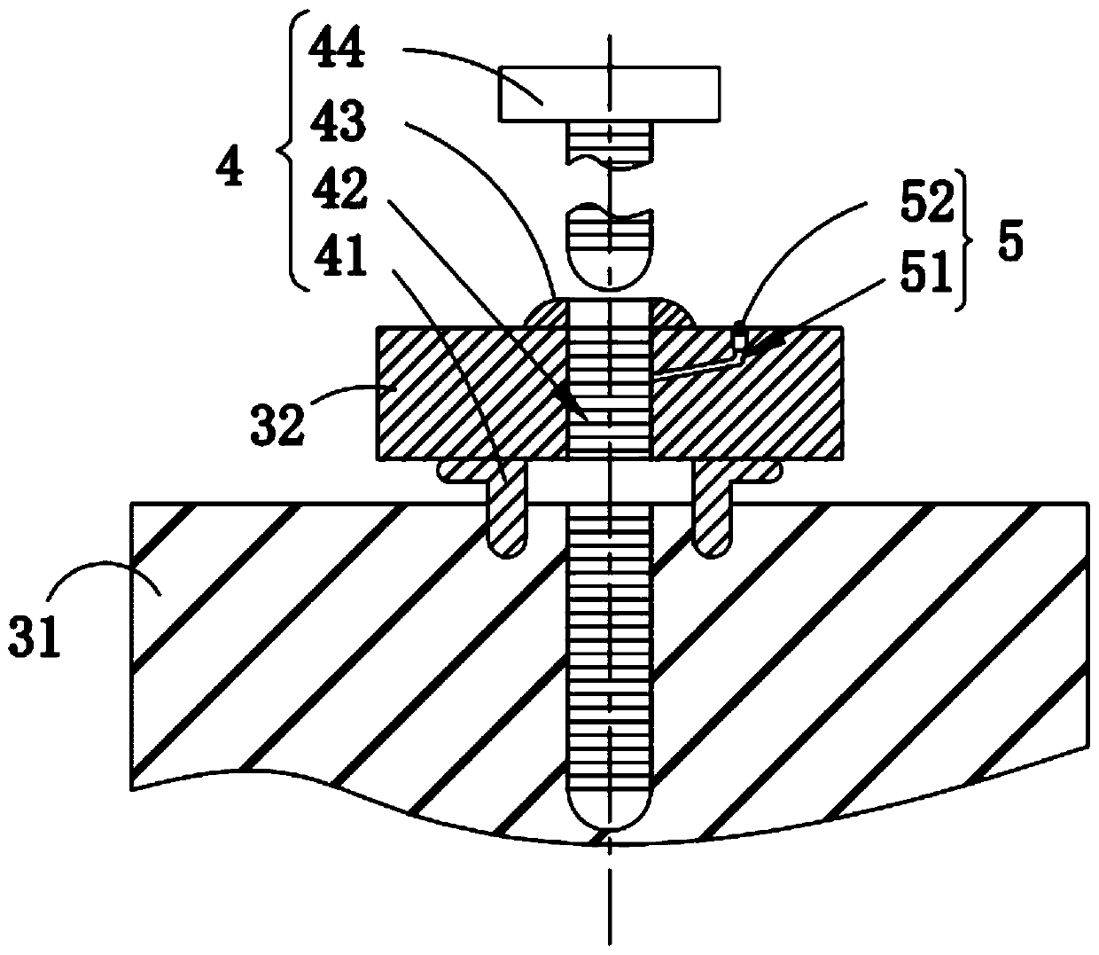
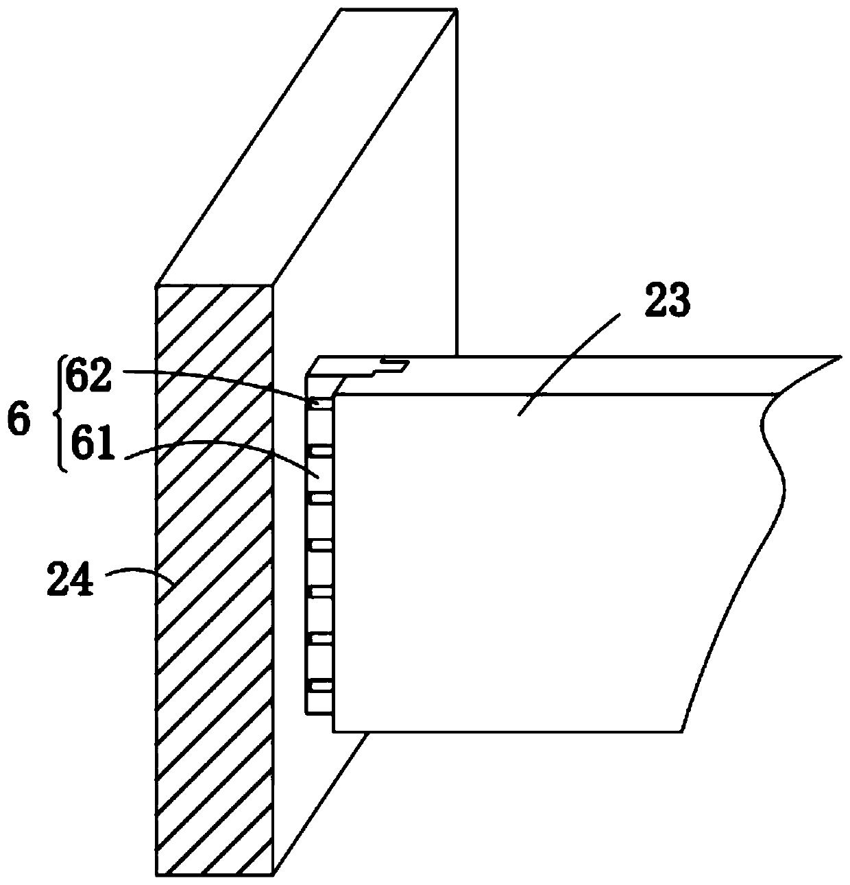
[0022] Please refer to figure 1 , figure 2 with image 3 ,among them, figure 1 It is a schematic structural diagram of the first embodiment of the finalized steel mold for construction provided by the present invention; figure 2 for figure 1 The shown decomposition diagram of the internal structure of the fixing mechanism; image 3 for figure 1 The schematic diagram of the connecting structure of the side plate and the baffle shown. The shaping steel mold for building includes: a supporting table 1; a first forming mechanism 2 fixed to the side wall of the supporting table 1, and the first forming mechanism 2 includes a bottom plate 21 and a fixed beam 22 , A baffle 23 and a side plate 24, the side wall of the support 1 is installed with the bottom plate 21 obliquely, the two ends of the bottom plate 21 are symmetrically installed with the side plate 24, and the top end of the side plate 24 is engaged with the Support platform 1; the side walls of the side plate 24 are equidis...
Embodiment approach
[0023] As a preferred embodiment of the present invention, the connecting mechanism 3 includes a supporting plate 31 and a connecting plate 32. The bottom surface of the bottom plate 21 is installed with the supporting plate 31 equidistantly, and the side walls of the side plate 24 are installed equidistantly. The connecting plate 32, the connecting plate 32 abuts the supporting plate 31, in order to facilitate the connection of the side plate 24 and the bottom plate 21, the supporting plate 31 and the connecting plate 32 are used to connect the side plate 24 is fixed on the top surface of the bottom plate 21 to facilitate people to pour concrete.
[0024] As a preferred embodiment of the present invention, the side wall of the fixed beam 22 is an I-shaped structure, and the fixed beam 22 is connected to the top surface of the support table 1, in order to strengthen the stability of the fixed beam 22 , Make the fixed beam 22 fix the baffle 23 to prevent the baffle 23 from shaking...
no. 2 example
[0033] See 4. figure 2 It is a schematic structural diagram of the second embodiment of the shaped and tempered steel mold for construction provided by the present invention. Based on the shaped and tempered mold for construction provided by the first embodiment of the present invention, the difference between the shaped and tempered mold for construction provided by the second embodiment of the present invention is that the shaped and tempered mold for construction includes: a fixed plate 7; The second forming mechanism 8, the bottom end of the second forming mechanism 8 is mounted with the fixing plate 7, the second forming mechanism 8 includes a horizontal plate 81 and a vertical plate 82, the horizontal plate 81 and the vertical plate 82 The inner side wall of the bottom end is installed with the fixed plate 7 with an inclined top surface, and the horizontal plate 81 and the vertical plate 82 are connected perpendicularly to each other.
[0034] As a preferred embodiment of ...
PUM
 Abstract
Description
Claims
Application Information
 - R&D Engineer
- R&D Manager
- IP Professional
- Industry Leading Data Capabilities
- Powerful AI technology
- Patent DNA Extraction
Browse by: Latest US Patents, China's latest patents, Technical Efficacy Thesaurus, Application Domain, Technology Topic.
© 2024 PatSnap. All rights reserved.Legal|Privacy policy|Modern Slavery Act Transparency Statement|Sitemap