Radial-axial permanent magnetic bearing system device
What is Al technical title?
Al technical title is built by PatSnap Al team. It summarizes the technical point description of the patent document.
A technology of permanent magnetic bearings and system devices, which is applied in the direction of shafts and bearings, bearings, bearing components, etc., can solve the problem that permanent magnetic bearings cannot bear radial force and axial force at the same time, and achieve good axial bearing capacity, good Radial load capacity and long life effect
Active Publication Date: 2019-11-22
SHANGHAI UNIV
View PDF16 Cites 4 Cited by
Summary
Abstract
Description
Claims
Application Information
AI Technical Summary
This helps you quickly interpret patents by identifying the three key elements:
Problems solved by technology
Method used
Benefits of technology
Problems solved by technology
[0003] In order to overcome the shortcomings that the existing single-structure permanent magnetic bearings cannot bear radial force and axial force at the same time, the purpose of the present invention is to provide a radial axial permanent magnetic bearing system device that can simultaneously bear radial force and axial force
Method used
Image
Click on the blue label to locate the original text in one second.
Reading with bidirectional positioning of images and text.
Examples
Embodiment Construction
[0014] Specific embodiments of the present invention will be described in detail below in conjunction with the accompanying drawings.
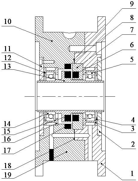
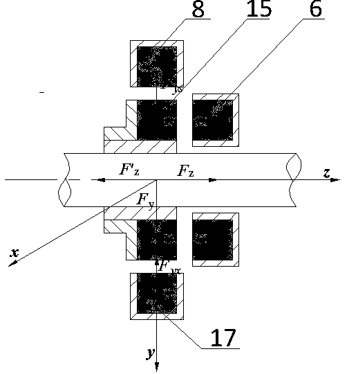
[0015] Such as figure 1 and figure 2 As shown, a radial and axial permanent magnetic bearing system device includes a right bearing seat 1, a right end cover 2, a right cooling jacket 3, a right top seat 4, a right auxiliary angular contact ball bearing 5, an axial static magnetic ring 6, and a shaft Static magnetic ring seat 7, static semi-magnetic ring seat 8 radially, sealing ring 9, static semi-magnetic ring seat 10 radially upward of the left bearing, left end cover 11, left top seat 12, dynamic magnetic ring seat 13 of the inner ring of the permanent magnet bearing, Left auxiliary angular contact ball bearing 14, moving magnetic ring 15, left cooling jacket 16, radially lower static semi-magnetic ring 17, sealing ring 18, radially lower static semi-magnetic ring seat 19 of the left bearing; the inner ring of the permanent magnetic bear...
PUM
Abstract
The invention discloses a radial-axial permanent magnetic bearing system device. The radial-axial permanent magnetic bearing system device comprises a right bearing seat, a right end cover, a right cooling sleeve, a right top seat, a right auxiliary angle contact ball bearing, an axial static magnetic ring, an axial static magnetic ring seat, a radial upper static semi-magnetic ring, a sealing ring, a left bearing radial upper static semi-magnetic ring seat, a left end cover, a left top seat, a permanent magnet bearing inner ring moving magnetic ring seat, a left auxiliary angle contact ball bearing, a moving magnetic ring, a left cooling sleeve, a radial lower static semi-magnetic ring, a sealing ring, a left bearing radial lower static semi-magnetic ring seat and the like. The device further comprises an auxiliary mechanical control protection system composed of a series of parts such as an auxiliary bearing except a combination device composed of the radial permanent magnet bearingand the axial permanent magnet bearing, the device can overcome the defect that a traditional permanent magnet bearing is single in structure and cannot bear the radial-axial composite load in actualapplication, and the application range of the permanent magnet bearing is expanded. The device has the advantages of being compact in structure, high in rotating speed, long in service life and the like, not only has good radial bearing capacity, but also has good axial bearing capacity.
Description
technical field [0001] The invention belongs to the technical field of magnetic suspension bearings, and in particular relates to a radial and axial permanent magnetic bearing system device. Background technique [0002] The relative moving parts (inner and outer rings, inner and outer rings and rolling elements) of the existing types of sliding bearings and rolling bearings are in direct contact with each other, which have relatively large frictional resistance and are prone to heat generation. However, the axial or radial permanent magnetic bearings with a single structure have overcome the shortcomings of the above traditional mechanical bearings, but they cannot meet the needs of bearing the actual middle-diameter and axial compound loads, because for a single The structure of the radial permanent magnetic bearing is stable in the radial direction between the two magnetic rings, and the small displacement in the radial direction can automatically return to a stable posit...
Claims
Application Information
Patent Timeline
Application Date:The date an application was filed.
Publication Date:The date a patent or application was officially published.
First Publication Date:The earliest publication date of a patent with the same application number.
Issue Date:Publication date of the patent grant document.
PCT Entry Date:The Entry date of PCT National Phase.
Estimated Expiry Date:The statutory expiry date of a patent right according to the Patent Law, and it is the longest term of protection that the patent right can achieve without the termination of the patent right due to other reasons(Term extension factor has been taken into account ).
Invalid Date:Actual expiry date is based on effective date or publication date of legal transaction data of invalid patent.