Radial rigidity adjusting method and structure for liquid rubber composite joints

A technology of liquid rubber and radial stiffness, applied in the field of rail transit, can solve the problems of low stiffness performance, large wear of wheel rails and lines, and difficult to realize, and achieve the effect of improving critical speed and curve passing performance and reducing wear

Inactive Publication Date: 2019-11-22
ZHUZHOU TIMES RUIWEI ANTI VIBERATION EQUIP LTD
View PDF9 Cites 10 Cited by
  • Summary
  • Abstract
  • Description
  • Claims
  • Application Information

AI Technical Summary

Problems solved by technology

[0002] According to the dynamic requirements, when the pivoting arm node is running in a straight line at high speed (high frequency vibration), it provides a large radial stiffness to ensure the running stability and increase the critical speed; when it passes the curve (low frequency and large amplitude), it provides a small stiffness performance Guarantee over-curve performance and reduce wear; it is difficult for ordinary joints to achieve the above characteristics, especially for old lines, where the wear of wheels, rails and lines is high, and the maintenance cost is high. Therefore, it is necessary to use a new product that has the above characteristics at the same time—liquid rubber composite joints

Method used


Image

  • Radial rigidity adjusting method and structure for liquid rubber composite joints
  • Radial rigidity adjusting method and structure for liquid rubber composite joints
  • Radial rigidity adjusting method and structure for liquid rubber composite joints

Examples


Embodiment 1

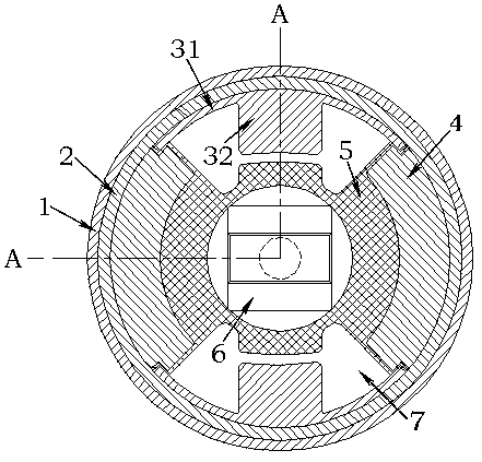
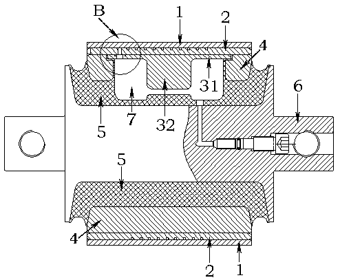
[0023] Such as figure 1 , figure 2 and image 3 As shown, the liquid rubber composite node includes an overall casing 1 , a runner casing 2 , a cover plate, an intermediate spacer 4 , a rubber body 5 and a mandrel 6 . The rubber body 5 is vulcanized between the middle spacer 4 and the mandrel 6, so that the middle spacer 4, the rubber body 5 and the mandrel 6 are connected as a whole. The cover plate includes an arc-shaped plate 31 and a protrusion 32 , and the protrusion 32 is arranged in the middle of the inner side of the arc-shaped plate 31 . The two ends on the outside of the middle spacer 4 are provided with a step mouth, and a rubber body 5 is vulcanized at the step mouth, and the two ends of the arc plate 31 are covered on the rubber body 5 at the step mouth, and the cover plate, the middle spacer 4, The rubber body 5 is assembled into the runner casing 2 together with the mandrel 6 . A liquid cavity 7 is provided between the cover plate and the rubber body 5 , an...

Embodiment 2

[0033] Such as Figure 4 As shown, the main difference between this embodiment and Embodiment 1 is that the stopper stiffness adjustment structure is different from Embodiment 1, and the mandrel 6 of this embodiment is set at a position corresponding to the arc-shaped plate 31 in the radial direction. A protrusion is formed, and when the liquid rubber composite node is deformed, the rubber body 5 at the protrusion contacts with the arc plate 31 to produce variable stiffness. Because the thickness of the protruding vulcanized rubber body 5 of the mandrel 6 in this embodiment is relatively small, when the rubber body 5 touches the curved plate 31, the effect of a sudden increase in rigidity is obvious, and a hard stop can be quickly provided. function, allowing the stiffness to increase dramatically in a short period of time.

Embodiment 3

[0035] Such as Figure 5 As shown, the main difference between this embodiment and Embodiment 1 is that the stopper stiffness adjustment structure is different from Embodiment 1, and the rubber body 5 of this embodiment is arranged at a position corresponding to the arc-shaped plate 31 in the radial direction. A bulge is formed, and when the liquid rubber composite node is deformed, the bulge of the rubber body 5 touches the curved plate 31 to produce a variable stiffness. Since the thickness of the rubber body 5 in this embodiment is very large, although the rubber body 5 abuts against the arc-shaped plate 31 can produce variable stiffness, the increase in stiffness is not obvious. Also because the thickness of the rubber body 5 is very large, after the protrusion of the rubber body 5 touches the curved plate 31, the change in the space stiffness of the liquid rubber composite joint is relatively gentle, and there is a good stability in the space direction of the liquid rubbe...


PUM


Abstract

The invention provides a radial rigidity adjusting method and structure for liquid rubber composite joints. Rubber bodies are vulcanized between middle spacer bushes and a mandrel; the two ends of a cover plate are closed on the middle spacer bushes in a covering manner, and the cover plate, the middle spacer bushes, the rubber bodies and the mandrel are together assembled into a flow channel outer sleeve; liquid cavities are formed between the cover plate and the rubber bodies, so that the liquid cavities are partitioned by the middle spacer bushes; the cover plate and the flow channel outersleeve are provided with liquid channels, and the liquid channels are enabled to communicate the partitioned liquid cavities with each other; and liquid is injected into the liquid cavities and the liquid channels. Due to the radial rigidity adjusting method and structure for the liquid rubber composite joints, by changing the shapes and the sizes of the liquid cavities and the liquid channels, the empty direction rigidity of the liquid rubber composite joints in the radial direction is adjusted, especially, the movable rigidity of the liquid rubber composite joints in the high-frequency stateand in the low-frequency state is adjusted, the critical speed and the through curve performance of vehicles are improved, and the abrasion is reduced.

Description

technical field [0001] The invention relates to the field of rail transit, in particular to a method and structure for adjusting the stiffness of a liquid rubber composite node. Background technique [0002] According to the dynamic requirements, when the pivoting arm node is running in a straight line at high speed (high frequency vibration), it provides a large radial stiffness to ensure the running stability and increase the critical speed; when it passes the curve (low frequency and large amplitude), it provides a small stiffness performance Guaranteed over-curve performance and reduced wear; it is difficult for ordinary joints to achieve the above characteristics, especially for old lines, where wheel rails and lines wear a lot, and the maintenance cost is high. Therefore, it is necessary to use a new product that has the above characteristics at the same time—liquid rubber composite joints. Contents of the invention [0003] The technical problem to be solved by the ...

Claims


Application Information

Patent Timeline
Patent Type & Authority Applications(China)
IPC IPC(8): F16F13/18
CPCF16F13/18
Inventor 荣继刚罗俊唐运轮黄江彪曾先会陈俊辉李静曹广如
Owner ZHUZHOU TIMES RUIWEI ANTI VIBERATION EQUIP LTD
Why Eureka
Try Eureka