Locking, cooling and lubricating hydraulic system of heavy hydraulic automatic transmission

An automatic transmission, cooling and lubrication technology, applied in the direction of gear lubrication/cooling, transmission, components with teeth, etc. Solve problems such as the reduction of oil volume in the torque converter to the lubricating oil circuit, and achieve the effect of enhancing R&D capabilities, making full use of oil, and suppressing shock and vibration.

Active Publication Date: 2019-11-22
GUIZHOU UNIV
View PDF9 Cites 4 Cited by
  • Summary
  • Abstract
  • Description
  • Claims
  • Application Information

AI Technical Summary

Problems solved by technology

First of all, the oil flowing out of the oil pump directly leads to the clutch oil circuit. When the clutch is engaged, the oil pressure of the oil pump will increase to cause vibration and shock, and the stable oil pressure required by the clutch cannot be adjusted when the vehicle operating conditions change; secondly, When the torque converter is locked, the oil controlled by the pressure regulating valve of the main oil circuit and the pressure regulating solenoid valve of the main oil circuit will reduce the amount of oil from the torque converter to the lubricating oil circuit, which cannot guarantee the oil required by the lubricating oil circuit. The amount of oil, which in turn affects the cooling and lubricating work of the entire transmission system; finally, in a hydraulic torque converter bypass oil circuit connected in parallel to the clutch oil circuit, when the oil pump speed changes, the oil supply of the torque converter will also change, and the safety and reliability of torque converter operation cannot be guaranteed

Method used


Image

  • Locking, cooling and lubricating hydraulic system of heavy hydraulic automatic transmission
  • Locking, cooling and lubricating hydraulic system of heavy hydraulic automatic transmission

Examples


Embodiment Construction

[0019] The locking and cooling lubricating hydraulic system of the heavy-duty hydraulic automatic transmission provided by the present invention will be described in detail below in conjunction with the accompanying drawings. It is an optional embodiment of the present invention. It can be considered that those skilled in the art will not change the It can be modified and polished within the scope of the spirit and content of the invention.

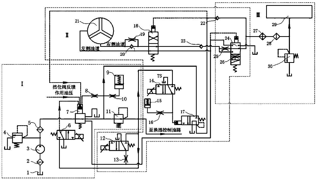
[0020] Such as figure 1 As shown, the locking and cooling and lubricating hydraulic system of the heavy-duty hydraulic automatic transmission of the present invention is composed of three parts: the main pressure regulating system, the torque converter locking control system and the cooling and lubricating system. The working principles of these three parts are introduced respectively below.

[0021] The main function of the main pressure regulating system of the heavy-duty hydraulic automatic transmission is to automatically adjust acc...


PUM


Abstract

The invention discloses a locking, cooling and lubricating hydraulic system of a heavy hydraulic automatic transmission. The locking, cooling and lubricating hydraulic system is composed of a main pressure regulating system, a converter locking control system and a cooling and lubricating system. According to the locking, cooling and lubricating hydraulic system, a converter auxiliary oil supply oil way composed of a gear shifting detection electromagnetic valve and a throttling valve is additionally arranged in a main oil supply oil way from a main pressure regulating valve to a converter anda control oil way of a pressure reducing valve, and during gear shifting of a vehicle, oil liquid is supplied to the converter by the auxiliary converter oil way so that working and service life of the converter of the heavy hydraulic automatic transmission can be effectively and safely guaranteed. A buffer oil way composed of a throttling valve and an energy accumulator is connected in parallelin each of the main pressure regulating system and the converter locking control system, so that impact and vibration generated in the working of the main pressure regulating system and the converterlocking control system are effectively reduced or inhibited, and the working performance and quality of the system are greatly improved.

Description

technical field [0001] The invention relates to a system oil circuit, in particular to a locking and cooling lubricating hydraulic system of a heavy-duty hydraulic automatic transmission, that is, to the locking control and control of the hydraulic torque converter of the heavy-duty hydraulic automatic transmission. The transmission is cooled and lubricated. [0002] technical background [0003] The hydraulic automatic transmission is composed of a hydraulic torque converter, a planetary gear transmission group, a hydraulic system and an electronic control system and has a transmission device within a certain speed ratio range. Among them, the hydraulic torque converter (HYDRAULIC CONVERTER) is a hydraulic transmission device that changes the magnitude of the transmitted torque according to the change of the vehicle's driving conditions. [0004] figure 2 It is the torque converter oil circuit of an automatic transmission of a domestic company. The oil from the oil pump fl...

Claims


Application Information

Patent Timeline
Patent Type & Authority Applications(China)
IPC IPC(8): F16H57/04F16H61/14
CPCF16H57/0412F16H57/0434F16H61/14
Inventor 吴怀超曹刚赵丽梅褚园民
Owner GUIZHOU UNIV
Why Eureka
Try Eureka