Pressure loading device for high-pressure neutron diffraction

A loading device and neutron technology, applied in the direction of applying stable tension/pressure to test material strength, using wave/particle radiation for material analysis, measuring devices, etc., can solve problems such as anvil damage

Active Publication Date: 2019-11-22
SICHUAN UNIV
View PDF5 Cites 6 Cited by
  • Summary
  • Abstract
  • Description
  • Claims
  • Application Information

AI Technical Summary

Problems solved by technology

[0002] When performing in situ neutron diffraction experiments, under uniaxial loading, radial diffraction mode and sample volume greater than 10mm 3 Under the premise of the 30GPa ultra-high pressure cavity, it cannot be obtained by directly using the diamond on the platform surface to load the titanium-zirconium gasket on the anvil like the anvil cavity used for synchrotron radiation, because the titanium-zirconium gasket The strength is only 0.7GPa, and cannot be greater than 10mm 3 Realize 30GPa high-pressure chamber sealing under the premise of the sample
At present, the pressure chamber commonly used in high-pressure neutron diffraction in the world is composed of a ring-shaped concave anvil and a ring-shaped titanium-zirconium gasket. Although this pressure chamber can reach a cavity pressure of 25GPa under a load of 200 tons, the conventional The test generally does not exceed 20GPa, because when the load exceeds 150 tons, most of the experiments will be terminated due to the failure of the titanium-zirconium gasket, and the anvil will also be damaged

Method used


Image

  • Pressure loading device for high-pressure neutron diffraction
  • Pressure loading device for high-pressure neutron diffraction
  • Pressure loading device for high-pressure neutron diffraction

Examples


Embodiment

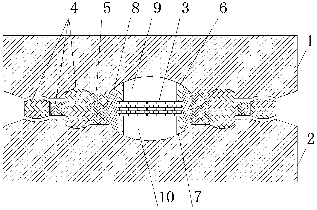
[0021] Such as figure 1 As shown, this embodiment provides a pressure loading device for high-pressure neutron diffraction, including an anvil assembly, the anvil assembly includes an upper anvil 1 and a lower anvil 2 with opposite anvil surfaces, an upper anvil 1, a lower anvil The anvil surface of the anvil 2 is respectively axially inwardly recessed relative to the upper anvil 1 and the lower anvil 2 to form an arc-shaped upper anvil surface and a lower anvil surface, and also includes a gasket assembly and a diamond pressurized sheet 3; the gasket assembly includes The outer cavity gasket 4, the cavity-forming gasket 5, and the cavity-inside gasket are sequentially arranged from outside to inside, wherein the cavity of the cavity-forming gasket 5 forms a pressure cavity with the upper anvil surface and the lower anvil surface, and the diamond pressurized sheet 3 It is arranged in the inner cavity of the cavity-forming gasket 5 and divides the pressure cavity into an upper ...


PUM

PropertyMeasurementUnit
thicknessaaaaaaaaaa
strengthaaaaaaaaaa

Abstract

The invention provides a pressure loading device for high-pressure neutron diffraction. The device comprises an anvil assembly. The anvil assembly comprises an upper anvil and a lower anvil with opposite anvil surfaces, the anvil surfaces of the upper anvil and the lower anvil are respectively sunken inwards relative to the axial directions of the upper anvil and the lower anvil to form an arc-shaped upper anvil surface and an arc-shaped lower anvil surface. The pressure loading device also comprises a sealing gasket assembly and a diamond pressurizing sheet, wherein the sealing gasket assembly is arranged between the two anvils, a pressure cavity is defined by an inner cavity of the sealing gasket assembly, the upper anvil face and the lower anvil face, and the diamond pressurizing pieceis arranged in the inner cavity of the sealing gasket assembly and divides the pressure cavity into an upper pressure cavity body and a lower pressure cavity body.

Description

technical field [0001] The invention belongs to the technical field of in-situ neutron diffraction devices, and in particular relates to a pressure loading device for high-pressure neutron diffraction. Background technique [0002] When performing in situ neutron diffraction experiments, under uniaxial loading, radial diffraction mode and sample volume greater than 10mm 3 Under the premise of the 30GPa ultra-high pressure cavity, it cannot be obtained by directly using the diamond on the platform surface to load the titanium-zirconium gasket on the anvil like the anvil cavity used for synchrotron radiation, because the titanium-zirconium gasket The strength is only 0.7GPa, and cannot be greater than 10mm 3 The premise of the sample is to achieve a 30GPa high-pressure chamber seal. At present, the pressure chamber commonly used in high-pressure neutron diffraction in the world is composed of a ring-shaped concave anvil and a ring-shaped titanium-zirconium gasket. Although t...

Claims


Application Information

Patent Timeline
Patent Type & Authority Applications(China)
IPC IPC(8): G01N23/207G01N23/20041G01N3/08G01N3/06G01N3/02
CPCG01N3/02G01N3/06G01N3/08G01N23/20041G01N23/2073G01N2203/0019G01N2203/0085G01N2203/0641
Inventor 贺端威胡启威
Owner SICHUAN UNIV
Why Eureka
Try Eureka