Check patentability & draft patents in minutes with Patsnap Eureka AI!

Backlight Module

A backlight module and light source technology, which is applied in optics, nonlinear optics, identification devices, etc., can solve problems such as difficult elimination, dark splicing lines, and affecting display quality, so as to ensure uniformity and improve splicing dark lines.

Active Publication Date: 2022-02-22
WUHAN CHINA STAR OPTOELECTRONICS TECH CO LTD
View PDF5 Cites 0 Cited by
  • Summary
  • Abstract
  • Description
  • Claims
  • Application Information

AI Technical Summary

Problems solved by technology

However, adjacent Mini LED light panels tend to produce obvious splicing gaps at the splicing places, and there will be splicing dark lines in the display, which are not easy to eliminate, affecting the display quality
[0004] Therefore, the existing Mini LED backlight module has the technical problem of splicing dark lines at the splicing of light panels, which needs to be improved.

Method used


Image

  • Backlight Module
  • Backlight Module
  • Backlight Module

Examples


Embodiment Construction

[0031] The following descriptions of the various embodiments refer to the accompanying drawings to illustrate specific embodiments in which the invention may be practiced. The directional terms mentioned in the present invention, such as [top], [bottom], [front], [back], [left], [right], [inside], [outside], [side], etc., are only for reference The orientation of the attached schema. Therefore, the directional terms used are used to illustrate and understand the present invention, but not to limit the present invention. In the figures, elements with similar structures are denoted by the same reference numerals.

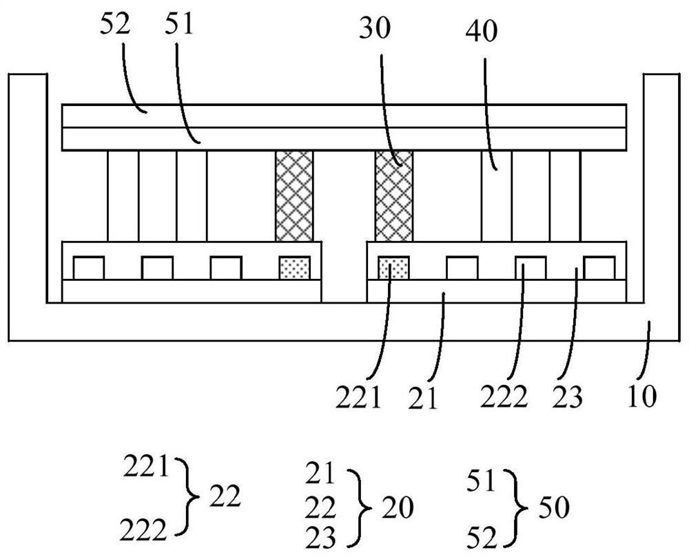
[0032] The invention provides a backlight module and a preparation method of the backlight module, so as to alleviate the technical problem of splicing dark lines at the splicing of lamp panels in the existing Mini LED backlight module.

[0033] Such as figure 1 As shown, it is a schematic diagram of the first structure of the backlight module provided by the embod...


PUM


Abstract

The invention provides a backlight module, which includes a backplane, a light source, a light guide column and an optical film. The backplane forms an accommodating cavity; The LED light bar includes a first LED light located in the splicing area; the optical film includes a diffuser, which is located in the accommodating cavity and arranged in the light-emitting direction of the light source; the light guide column is arranged in the splicing area, and Located in the light emitting direction of the light source, the light emitting surface of the light guide column corresponds to the light incident surface of the diffuser, the light guide column is a hollow structure, and the inner wall is provided with a reflective film. By arranging a light guide column on the first LED lamp in the splicing area, the light emitted by the first LED lamp enters the light guide column, is reflected by the reflective film, and is transmitted to the diffuser in the optical film, and the light is transmitted horizontally in the diffuser. Mixing light, thus ensuring the uniformity of brightness at the splicing place, and improving the phenomenon of splicing dark lines at the splicing place.

Description

technical field [0001] The invention relates to the field of display technology, in particular to a backlight module. Background technique [0002] Mini LED (Mini LED) is regarded as a new generation due to its advantages of self-illumination, small size, light weight, high brightness, longer life, lower power consumption, faster response time, and stronger controllability. display technology. [0003] The size of the Mini LED light board is usually small, and the Mini LED backlight module in the medium-sized display device is mostly made by splicing multiple Mini LED light boards. However, the splicing of adjacent Mini LED light panels tends to produce obvious splicing gaps, and there will be splicing dark lines during display, which are not easy to eliminate, affecting the display quality. [0004] Therefore, the existing Mini LED backlight module has the technical problem of splicing dark lines at the splicing of light panels, which needs to be improved. Contents of t...

Claims


Application Information

Patent Timeline
Patent Type & Authority Patents(China)
IPC IPC(8): G02F1/13357G09F9/30
CPCG02F1/133603G02F1/133606G02F1/133605G02F1/133611G09F9/30
Inventor 杨勇
Owner WUHAN CHINA STAR OPTOELECTRONICS TECH CO LTD
Features
  • R&D
  • Intellectual Property
  • Life Sciences
  • Materials
  • Tech Scout
  • Unparalleled Data Quality
  • Higher Quality Content
  • 60% Fewer Hallucinations
Learn More