
Shear wave imaging based on ultrasound with increased pulse repetition interval

An ultrasonic imaging system and shear wave technology, applied in ultrasonic/sonic/infrasound image/data processing, ultrasonic/sonic/infrasonic diagnosis, ultrasonic/sonic/infrasonic equipment control, etc., can solve problems such as errors

Active Publication Date: 2019-11-26
SIEMENS MEDICAL SOLUTIONS USA INC
View PDF5 Cites 0 Cited by
  • Summary
  • Abstract
  • Description
  • Claims
  • Application Information

AI Technical Summary

Problems solved by technology

This method can suffer from artifacts caused by clutter noise from different separable tracking transmissions and from errors caused by displacement estimation using transmitted pulses with different frequencies or codes

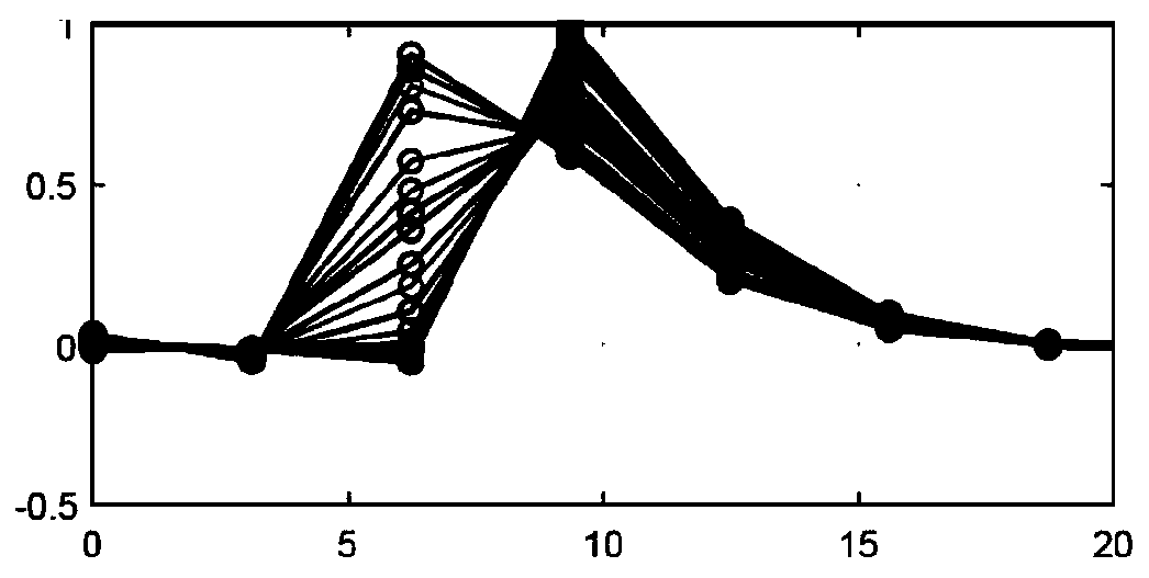
Method used


Image

  • Shear wave imaging based on ultrasound with increased pulse repetition interval
  • Shear wave imaging based on ultrasound with increased pulse repetition interval
  • Shear wave imaging based on ultrasound with increased pulse repetition interval

Examples


Embodiment Construction

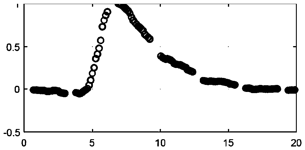
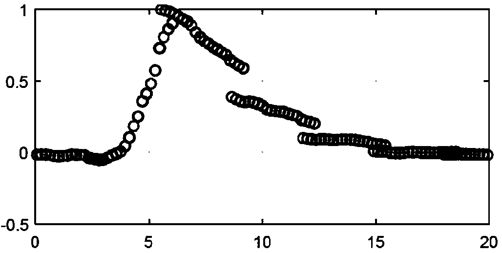
[0013] Provides shear wave imaging with ultrasound in highly rigid media. Examples of such rigid media in medical imaging include musculoskeletal (MSK) (e.g. tendon), prostate, and focal lesions of the liver. By increasing the apparent PRF, shear wave velocity can be estimated more accurately even if the ultrasonic round-trip travel time results in undersampling of a given location. The same approach can be used in less rigid media where tracking frequency is not an issue. This approach increases the effective PRF, leading to potentially more accurate shear wave velocity estimates.

[0014] Displacement profiles from multiple lateral positions are combined. Displacement profiles from different lateral locations are time-shifted and scaled based on possible shear-wave velocities and attenuations. The time shifted and scaled distributions are combined to form a displacement distribution with a higher effective PRF. Shear wave velocity is calculated by finding the time offset...


PUM


Abstract

For shear wave imaging with ultrasound, the apparent pulse repetition frequency is increased by combining (14) displacements from different lateral locations. Different combinations based on differentshear wave velocities and corresponding time shifts and / or attenuations and corresponding scalings are tested to find a smooth displacement profile for the combination. Once the smooth displacement profile is found, the corresponding shear wave velocity is estimated or determined (18).

Description

Background technique [0001] This example relates to shear wave imaging using ultrasound. In shear wave elastography (SWEI), images are formed by tracking tissue displacements induced by shear waves induced by acoustic radiation force fluctuations (ARFI). The maximum pulse repetition frequency (PRF) used to track shear waves is determined by the round-trip time of the tracking pulse. In a highly rigid medium such as tendon, shear waves travel faster than in soft tissue. The maximum PRF may not be sufficient to track fast shear waves. [0002] Higher PRFs can be provided by tracking shear waves using a series of separable signals transmitted in rapid succession. For example, using tracking pulses at different frequencies or encoded transmit pulses to increase the sampling rate. This approach can suffer from artifacts caused by clutter noise from different separable tracking transmissions and from errors caused by displacement estimation using transmitted pulses with differen...

Claims


Application Information

Patent Timeline
IPC IPC(8): A61B8/00A61B8/08
CPCA61B8/085A61B8/485A61B8/5207A61B8/44A61B8/5223G16H50/30A61B8/54
Inventor Y.拉拜德
Owner SIEMENS MEDICAL SOLUTIONS USA INC
Learn More