External desulfurization circulating spraying system

A cyclic spraying, external technology, applied in the separation of dispersed particles, chemical instruments and methods, separation methods, etc., can solve the problems of increasing gas-liquid full contact, scouring of spray layer support beams, wasting energy and energy consumption, etc. Enhance the effect of stable performance, good locking, and good limit use

Pending Publication Date: 2019-11-26
山东普净环保工程有限公司
View PDF0 Cites 0 Cited by
  • Summary
  • Abstract
  • Description
  • Claims
  • Application Information

AI Technical Summary

Problems solved by technology

[0004] The purpose of the present invention is to provide an external desulfurization circulating spray system to solve the above-mentioned background technology. The supporting beam, the spraying direction of the nozzle is downward, and the slurry sprayed from the nozzle of the spray layer along the wall of the absorption tower flows along the wall of the absorption tower to the slurry pool area at the bottom of the tower. The slurry does not play a role in desulfurization and is wasted A large amount of energy and energy consumption, from the perspective of energy saving in operation, increase the full contact of gas and liquid, improve the desulfurization efficiency of the desulfurization device, reduce the operation and transformation costs of the desulfurization system, and put forward higher requirements for the desulfurization device. In addition, multi-layer spraying In terms of layer configuration, the general liquid sprayed downwards from the upper spray layer will cause scour to the lower spray layer, spray layer support beams, etc.

Method used


Image

  • External desulfurization circulating spraying system
  • External desulfurization circulating spraying system
  • External desulfurization circulating spraying system

Examples


example 1

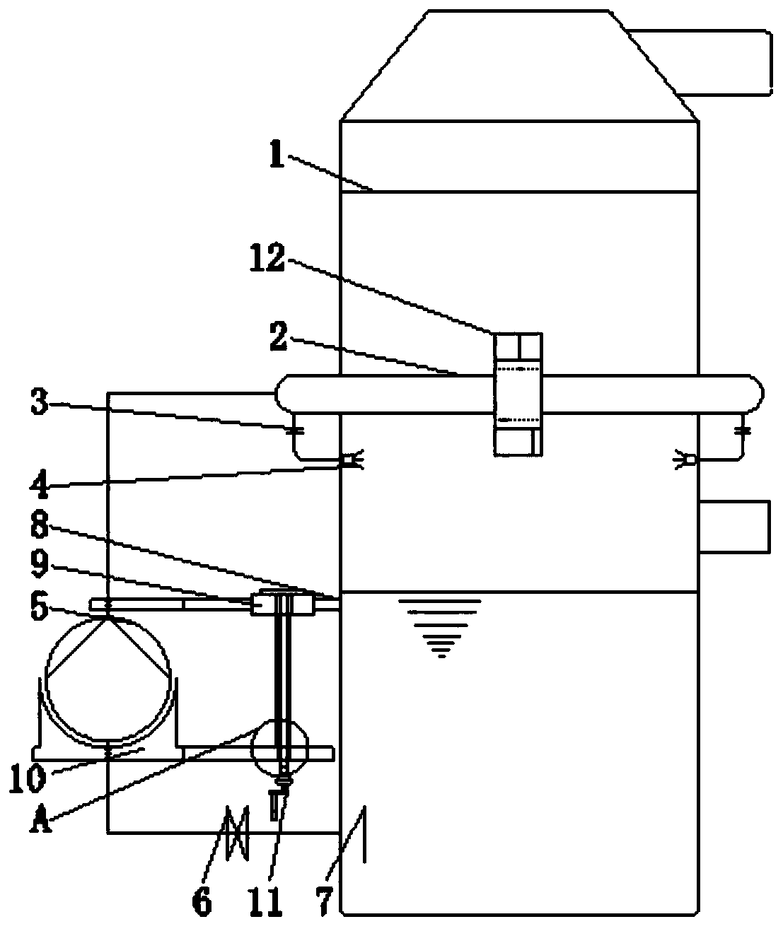
[0025] Its structure is mainly to arrange the slurry circulation main pipe outside the tower, the spray main pipe is arranged circumferentially, and the branch pipes are evenly distributed at the lower part of the main pipe according to the angle, and the nozzle 4 is arranged at the end of the branch pipe, and the nozzle 4 is inserted into the absorption tower. The spray main pipe can be rubber-lined pipe or glass fiber reinforced plastic pipe, the spray branch pipe is made of glass fiber reinforced plastic pipe, the nozzle 4 adopts the spiral cone atomizing nozzle 4 with a spray angle of 120 degrees, and the atomized droplets of the conical structure sprayed by the nozzle 4, in order to ensure All the flue gas passes through the layer of atomized droplets, and the atomized droplets must cover the entire section of the absorption tower;

[0026] After adopting the desulfurization technology of the external desulfurization circulation spray system, the nozzles 4 are all arranged...


PUM


Abstract

The invention discloses an external desulfurization circulating spraying system. The system comprises a desulfurizing absorption tower and a safety protection mechanism, the outer end of the middle part of the desulfurizing absorption tower is connected with a circulating mother tube outside the tower, spraying branch tube overhaul valves are arranged at the bottom ends of the circulating mother tube outside the tower, a nozzle is mounted at the outer end of every spraying branch tube overhaul valve, circulating pumps are arranged at the left end and the right end of the bottom end of the desulfurizing absorption tower, the bottom end of the desulfurizing absorption tower is connected with a circulating pump inlet shut-off valve, an inlet filter screen is installed at the bottom end of thecirculating pump inlet shut-off valve, the safety protection mechanism is located at the outer side of the circulating pumps, and a locking mechanism is mounted at the outer side of the circulating mother tube outside the tower. The external desulfurization circulating spraying system makes a safety protection fixing plate and a rocking rod rotate relative to each other through movably connectingthe safety protection fixing plate and the rocking rod, so the rocking rod is rotated and adjusted to carry out transmission operation, and the safety protection fixing plate is stably used by fixingthe safety protection fixing plate and the desulfurizing absorption tower.

Description

technical field [0001] The invention relates to the technical field of an external desulfurization circulating spray system, in particular to an external desulfurizing circulating spray system. Background technique [0002] The desulfurization technology currently implemented in China, whether it is a power plant, a steel mill, or a coking enterprise, has set higher requirements on the emission concentration of sulfur dioxide, and the emission concentration of sulfur dioxide is 35mg / Nm3 or lower. With higher requirements for sulfur dioxide emission concentration and wider industries for desulfurization, an external desulfurization circulation spray system desulfurization technology has emerged as the times require. [0003] The conventional desulfurization spray layer is the spray layer inside the tower, which adopts glass fiber reinforced plastic pipes or rubber-lined pipes. The pipe network and support beams are arranged inside, and the spraying direction of the nozzles is...

Claims


Application Information

Patent Timeline
Patent Type & Authority Applications(China)
IPC IPC(8): B01D53/14B01D53/18
CPCB01D53/1481B01D53/18
Inventor 王传军肖召刚
Owner 山东普净环保工程有限公司
Why Eureka
Try Eureka