Auxiliary equipment for drilling holes in the motor housing

A technology for motor casings and auxiliary equipment, which is applied in drilling/drilling equipment, metal processing equipment, boring/drilling, etc., and can solve problems such as inconsistent installation hole positions and low drilling efficiency

Active Publication Date: 2020-10-20
中擎电机有限公司
View PDF11 Cites 0 Cited by
  • Summary
  • Abstract
  • Description
  • Claims
  • Application Information

AI Technical Summary

Problems solved by technology

[0003] The motor casing is the main load-bearing part of the motor. The motor casing includes a hollow main body and a base on one side of the main body. When processing the motor casing, it is necessary to drill mounting holes at the end of the motor. Most of the existing methods are manual. The drilling rig drills one by one, so the positions of the installation holes are inconsistent, and the drilling efficiency is low. For this reason, an auxiliary equipment for drilling holes in the motor shell is needed

Method used


Image

  • Auxiliary equipment for drilling holes in the motor housing
  • Auxiliary equipment for drilling holes in the motor housing
  • Auxiliary equipment for drilling holes in the motor housing

Examples


Embodiment 1

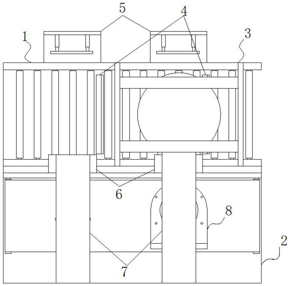
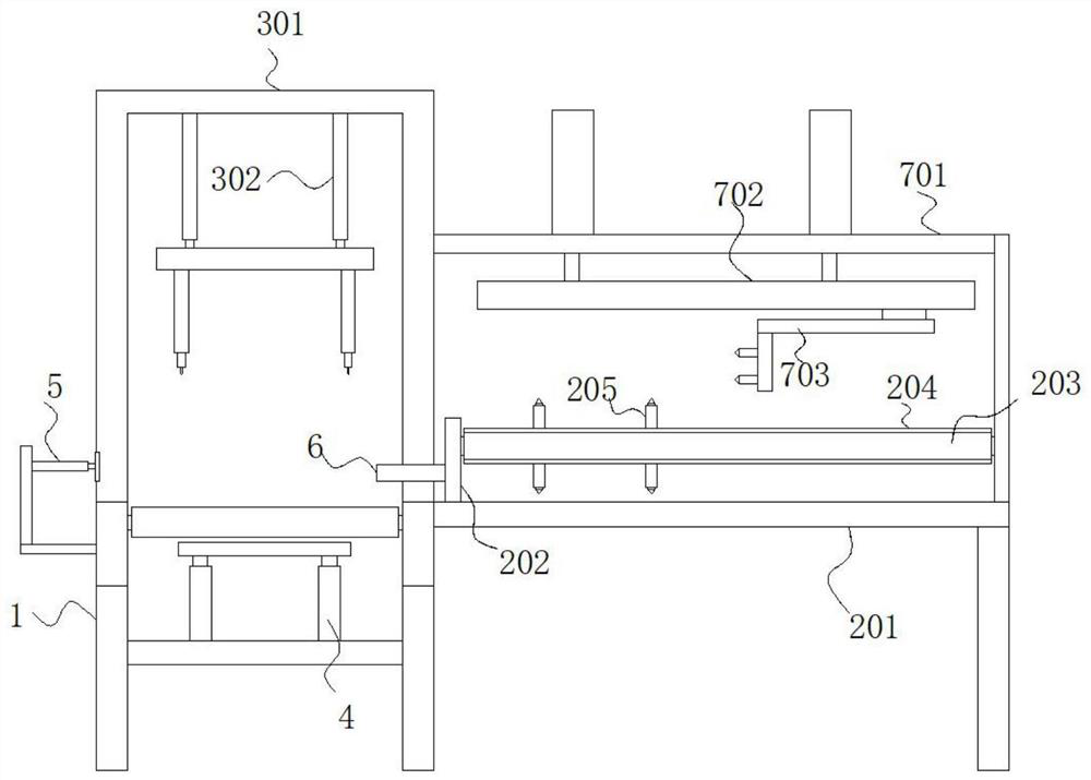
[0045] The conveying assembly 1 includes a bottom bracket, and the bottom bracket is fixedly connected to the support frame 201. Two groups of side baffles arranged in parallel are installed on both sides of the top of the bottom bracket, and there are movable sockets along the side baffles between the two groups of side baffles. The rollers are equidistantly arranged in the length direction, and the rollers are driven and connected by means of sprockets and chains;

Embodiment 2

[0047] The blocking assembly 4 includes a crossbeam affixed to the bottom bracket, a fourth driving mechanism is affixed to the top of the crossbeam, and an L-shaped blocking plate arranged parallel to the drum is affixed to the output end of the top of the fourth driving mechanism;

Embodiment 3

[0049] The push assembly 5 includes a side extension plate of an L-shaped structure fixed to the side baffle, and the side extension plate is located on the side of the bottom bracket away from the support frame 201, and the side extension plate is fixed on the side close to the support frame 201 There is a fifth driving mechanism arranged along the horizontal direction, and the output end of the fifth driving mechanism is fixedly connected with the active plate;


PUM


Abstract

The invention belongs to the technical field of motor production, and particularly relates to auxiliary equipment for hole forming of a motor shell. According to the technical scheme, the auxiliary equipment comprises a drilling assembly used for hole forming of the motor shell. A conveying assembly is fixedly connected to the bottom of the drilling assembly. Blocking assemblies located inside theconveying assembly are mounted below the input end and the output end of the drilling assembly. A material returning assembly arranged in the length direction of the conveying assembly is mounted onone side of the conveying assembly. Pushing assemblies fixedly connected with the conveying assembly are mounted on one sides, far away from the material returning assembly, of the two blocking assemblies and are located on one side, far away from the material returning assembly, of the conveying assembly. By means of the auxiliary equipment, drilling of end portion mounting holes of different motors is realized, adjustment is carried out according to the model of the motor shell and the positions of the mounting holes, convenience in adjustment is brought to an operator, the motor machining efficiency is improved, the consistency of the drilling of the mounting holes of the motor shell is improved, and the motor production efficiency is improved.

Description

technical field [0001] The invention relates to the technical field of motor production, in particular to auxiliary equipment for opening holes in motor shells. Background technique [0002] The motor refers to an electromagnetic device that realizes the conversion or transmission of electric energy according to the law of electromagnetic induction. During the production of the motor, each component of the motor needs to be processed separately and then assembled; [0003] The motor casing is the main load-bearing part of the motor. The motor casing includes a hollow main body and a base on one side of the main body. When processing the motor casing, it is necessary to drill mounting holes at the end of the motor. Most of the existing methods are manual. Drilling rigs are drilled one by one, so the positions of the mounting holes are inconsistent, and the drilling efficiency is low. For this reason, an auxiliary device for drilling holes in the motor shell is needed. Conte...

Claims


Application Information

Patent Timeline
Patent Type & Authority Patents(China)
IPC IPC(8): B23B39/16B23B41/00B23B47/00B23Q7/00B23Q7/05B23Q7/06
CPCB23B39/161B23B41/00B23B47/00B23Q7/00B23Q7/055B23Q7/06
Inventor 林波叶灵荣林娜金新兵叶云兰
Owner 中擎电机有限公司
Why Eureka
Try Eureka