
Motion mechanism, measurement system and method for wing flap load trial flight verification

A motion mechanism and flap technology, applied in the field of computer storage media, can solve the problems of high development cost, long cycle, complicated modification, etc., and achieve the effects of low cost, short cycle and strong anti-interference ability.

Active Publication Date: 2019-11-26
COMAC +1
View PDF5 Cites 6 Cited by
  • Summary
  • Abstract
  • Description
  • Claims
  • Application Information

AI Technical Summary

Problems solved by technology

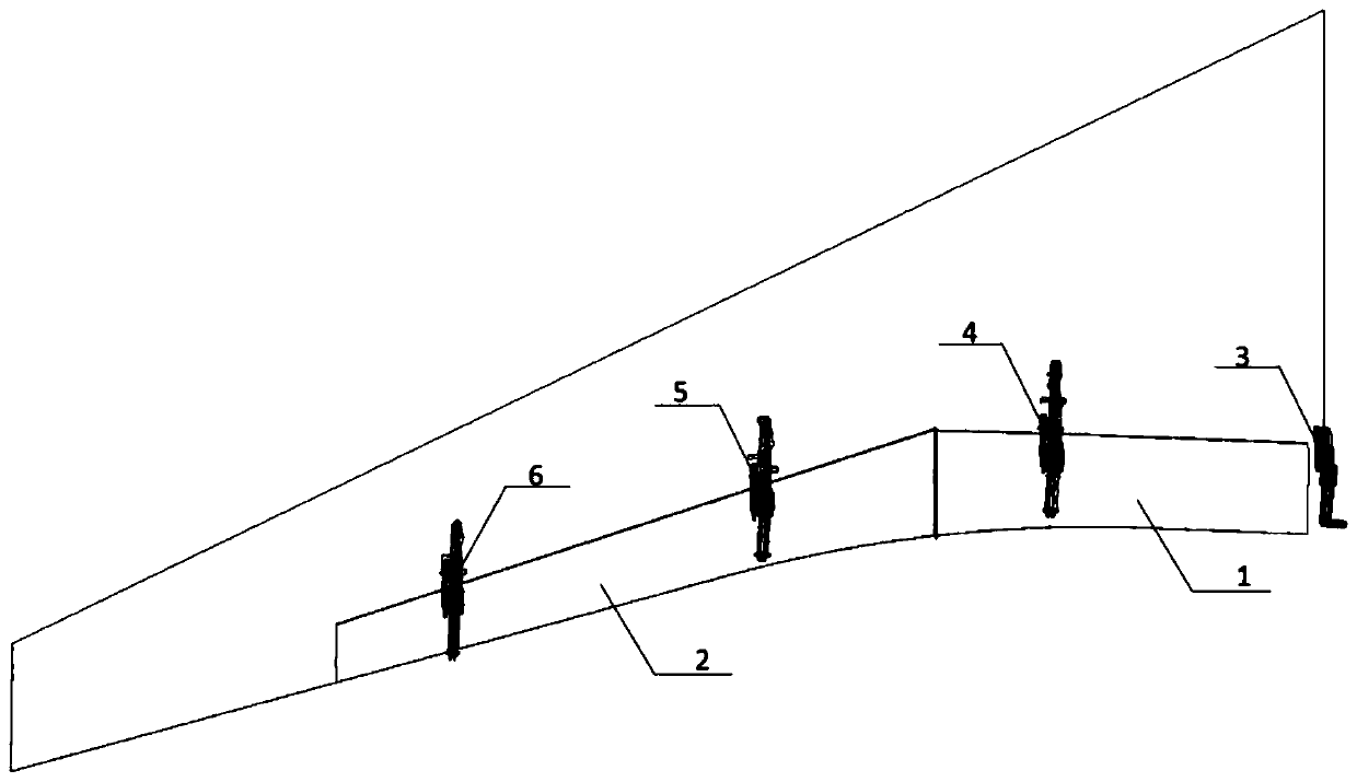
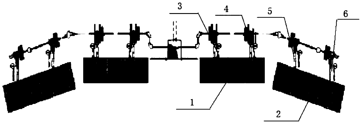
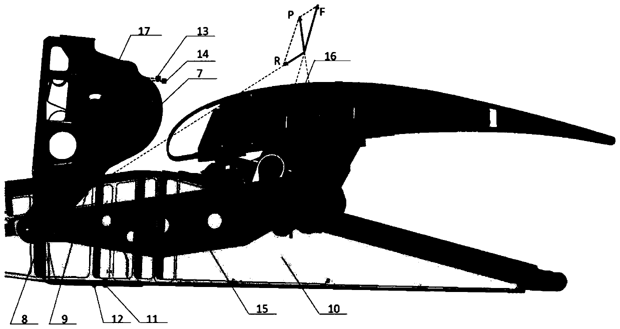
[0005] The present invention provides a kinematic mechanism, a measurement system, a corresponding method and a computer-readable medium for flap load test flight verification, which can overcome the development cost in the prior art High, long period and complex modification and other disadvantages, and provide higher precision flap load results for flight test verification

Method used


Image

  • Motion mechanism, measurement system and method for wing flap load trial flight verification
  • Motion mechanism, measurement system and method for wing flap load trial flight verification
  • Motion mechanism, measurement system and method for wing flap load trial flight verification

Examples


Embodiment Construction

[0046] The preferred embodiments of the present invention will be further described in detail below in conjunction with the accompanying drawings. The following descriptions are exemplary and not limiting to the present invention. Any other similar situations will also fall within the protection scope of the present invention. In the embodiments of the present invention, unless otherwise specified, the term "sensor" specifically refers to a flap load flight test sensor based on optical fiber strain measurement, for example, a Bragg grating strain sensor and a Bragg grating temperature sensor.

[0047] According to various embodiments of the present invention, a certain number of Bragg grating strain sensors and temperature sensors are arranged on all key connecting members between the flap and the wing, and high Accurate temperature-strain and load-strain correlation equations. The components that have passed the ground calibration / calibration test are replaced on the test air...


PUM


Abstract

The invention provides a motion mechanism for wing flap load trial flight verification. The motion mechanism is arranged between wing flaps and a wing structure and used for controlling motion of thewing flap relative to the wing structure. The motion structure comprises a load bearing component and a testing optical fiber, wherein the load baring component comprises a component used for bearingstress when driving the wing flaps to move relative to the wing structure, and further comprises bragg grating strain sensors and a bragg grating temperature sensor are arranged on stress measurementpoints; the testing optical fiber is used for connecting the bragg grating strain sensors and the bragg grating temperature sensor on the load bearing component of the motion mechanism in series; andthe testing optical fiber comprises an input end and an output end. The invention further provides a measurement system for wing flap load trial flight verification, a method for wing flap load trialflight verification and a computer storage medium.

Description

technical field [0001] The present invention relates to flap load test flight verification, more specifically, to a motion mechanism used in flap load test flight verification, a measurement system for flap load flight test verification, and a method for flap load flight test verification based on optical fiber strain measurement, and corresponding computer storage media. Background technique [0002] Due to the limitation of the length of the airport runway, the speed of the landing gear tires, and in order to improve the safety of aircraft take-off and landing, high-lift devices have been continuously developed and widely used in the design of modern large aircraft. In the initial stage of large aircraft development, the design loads of the flap structure, kinematic mechanism and its control system are generally determined by means of CFD (computational fluid dynamics) or low-speed wind tunnel pressure test data. The influence of flap configuration, slot parameters, and s...

Claims


Application Information

Patent Timeline
IPC IPC(8): B64F5/60
CPCB64F5/60
Inventor 黄勇魏腾飞邬旭辉任文广
Owner COMAC
Learn More