Head structure of a chute pintle injector

A technology of injector and pintle, which is applied in the field of pintle variable thrust engine design, can solve problems such as leakage of the pintle head and the mating surface of the cover plate, high process requirements, and difficult processing of injectors, etc., to achieve low The effect of propellant leakage rate, good experiment convenience, and reduced matching difficulty

Active Publication Date: 2021-01-12
XIAN AEROSPACE PROPULSION INST
View PDF6 Cites 0 Cited by
  • Summary
  • Abstract
  • Description
  • Claims
  • Application Information

AI Technical Summary

Problems solved by technology

[0003] At present, the nozzle hole configuration of ordinary pintle injectors is a straight groove or special-shaped groove structure. When designing the injector, the propellant flow rate, the leakage rate, the distance between the nozzle holes, the adjustment stroke of the pintle, and the structural strength of the pintle head Various design parameters are highly correlated, and the design of the injector is difficult; the structure of the head of the ordinary pintle injector is complex, and there is a risk of leakage between the pintle head and the mating surface of the cover plate, and the process requirements are high. Machine processing is difficult
When carrying out basic research such as atomization combustion, pintle injectors with fixed orifice sizes are often used for ground test pieces of pintle injectors, resulting in certain differences between the injector's working characteristics and actual adjustable pintle injector products

Method used


Image

  • Head structure of a chute pintle injector

Examples


Embodiment Construction

[0023] Below in conjunction with accompanying drawing and specific embodiment the present invention is described in further detail:

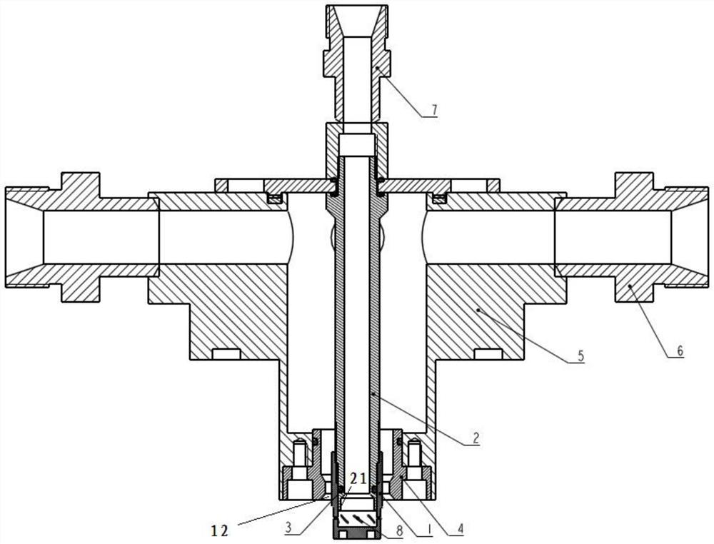
[0024] The present invention provides a head structure of a chute-type pintle injector, one type of injection medium enters the axial nozzle through the axial nozzle joint 7, and the other type of injection medium enters the pintle nozzle 1 through the radial nozzle joint 6; Finally, an atomized impact is formed outside the pintle nozzle 1; it can reduce the difficulty of matching the structural parameters of the pintle injector, improve the reliability of the pintle work and the convenience of the ground cold and hot state experiment.

[0025] Such as figure 1 Shown is a cross-sectional view of a chute-type pintle injector. It can be seen from the figure that a head structure of a chute-type pintle injector includes a pintle nozzle 1, a central rod 2, a sealing structure 3, and an outer ring cover plate 4 , an injector housing 5, n radial nozz...


PUM


Abstract

The invention discloses a skewed slot type pintle injector head structure, and relates to the field of pintle variable-thrust engine design. The skewed slot type pintle injector head structure comprises a pintle spray head, a center rod, a sealing structure, an outer ring cover plate, an injector shell, n radial nozzle connectors and an axial nozzle connector, wherein the injector shell is of a cylindrical structure; the pintle spray head is vertically and fixedly arranged in the middle of the lower end of the injector shell; the center rod is vertically and fixedly installed at the top end ofthe pintle spray head in the axial direction; the sealing structure is arranged at the joint between the pintle spray head and the center rod to achieve sealing; the outer ring cover plate is of an annular structure and fixedly installed at the lower portion of the injector shell; the n radial nozzle connectors are horizontally and uniformly arranged on the side wall of the injector shell in theaxial direction and communicate with an inner cavity of the injector shell; and the axial nozzle connector is vertically and fixedly installed at the top end of the center rod. According to the skewedslot type pintle injector head structure, the pintle injector structure parameter matching difficulty is lowered, and the pintle working reliability and the ground cold and hot state experiment convenience are improved.

Description

technical field [0001] The invention relates to the design field of a pintle variable thrust engine, in particular to a head structure of a chute type pintle injector. Background technique [0002] The variable-thrust liquid rocket engine technology can adapt to the recyclable and reused propulsion device; adapt to the overload control of astronauts in the active flight phase of manned spaceflight; adapt to space spacecraft rendezvous and docking and optimal orbit control; System control; adapt to the soft landing of extraterrestrial bodies such as the moon and Mars. Compared with the commonly used centrifugal or straight-line nozzles, the pintle injector has the outstanding advantage that the injection parameters can be adjusted in depth. It is used in many types of engines in the United States and my country's lunar landing engines. It can be recycled and reused in the future Engines have a definite need for thrust depth adjustment. The pintle engine is the most commonly ...

Claims


Application Information

Patent Timeline
Patent Type & Authority Patents(China)
IPC IPC(8): F02K9/52
CPCF02K9/52
Inventor 陈鹏飞杨岸龙王凯杨宝娥夏益志
Owner XIAN AEROSPACE PROPULSION INST
Why Eureka
Try Eureka