Pedal simulation device

A technology of pedal simulation and simulator, which is applied in the field of simulating foot feeling devices and linear braking systems, can solve the problems of increasing the complexity of hydraulic oil circuits, difficulty of installation, leakage of brake fluid, etc., and achieve reduction of pipeline interfaces and leakage risk, improve safety, and reduce matching difficulty

Pending Publication Date: 2018-04-10
ZHEJIANG LIBANG HEXIN INTELLIGENT BRAKING SYST CO LTD
View PDF11 Cites 3 Cited by
  • Summary
  • Abstract
  • Description
  • Claims
  • Application Information

AI Technical Summary

Problems solved by technology

This increases the complexity of the hydraulic oil circuit and the difficulty of installation, and the multi-pipe connectors have potential safety hazards of brake fluid leakage.

Method used


Image

  • Pedal simulation device
  • Pedal simulation device
  • Pedal simulation device

Examples


Embodiment 1

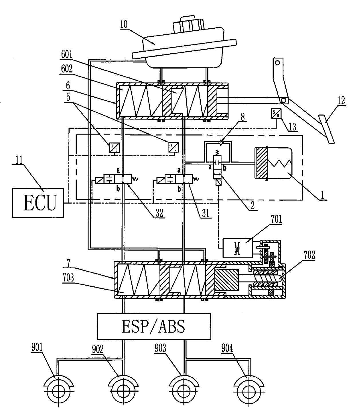
[0019] Embodiment 1: The brake master cylinder 6 is provided with two brake chambers, namely the first brake chamber 601 and the second brake chamber 602, and the normally open control valve 3 is correspondingly provided with two brake chambers. group, respectively normally open control valve A 31 and normally open control valve B 32, the ports a of the normally open control valve A 31 and normally open control valve B 32 are respectively connected to the first brake chamber 601 and the second brake chamber Chamber 602 is connected.

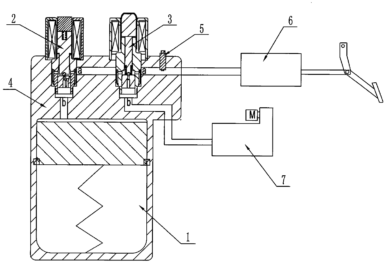
[0020] The b port of the oil inlet control valve 2 communicates with the simulator cylinder 1, and a check valve 8 is provided between the a port and the b port of the oil inlet control valve 2. In this embodiment, as Figure 4 As shown, the one-way valve 8 is arranged on the valve seat 21 of the oil inlet control valve 2. The one-way valve 8 includes a funnel-shaped pipeline 81 and a steel ball 82. The funnel-shaped pipeline is respectively larg...

Embodiment 2

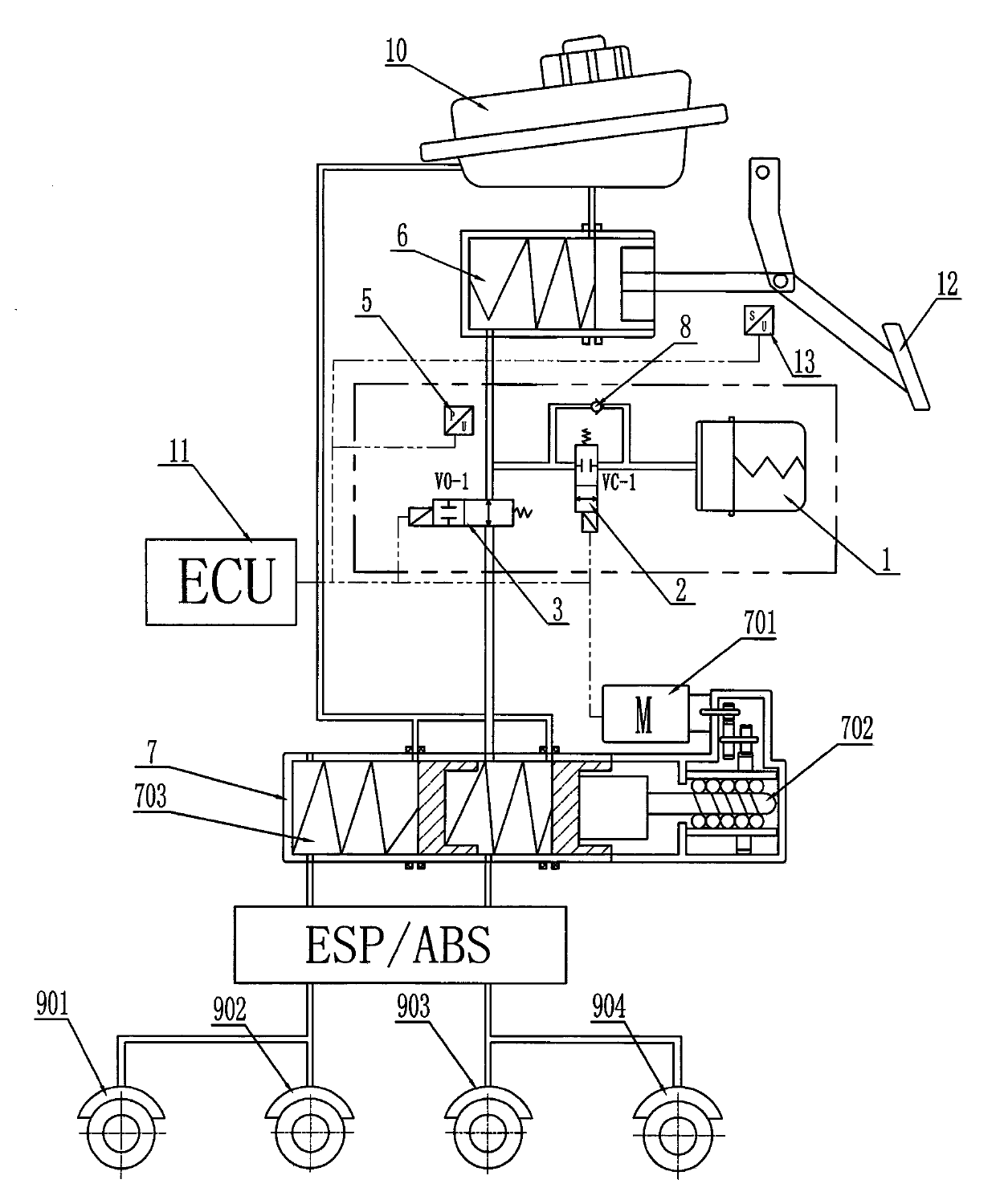
[0026] Embodiment two: if image 3 As shown, when the brake master cylinder adopts a single cylinder, a normally open solenoid valve and a hydraulic sensor can be reduced, that is to say, the brake master cylinder 6 is provided with a brake chamber, and the normally open control valve 3 is provided with one group correspondingly, and described hydraulic pressure sensor 5 also only needs to be provided with one group correspondingly, and the others remain unchanged.

[0027] Working principle: During normal braking, when the driver depresses the brake pedal, the stroke sensor detects the driver's braking intention and feeds back to the ECU. The brake master cylinder operates, and the brake fluid flows into the normally open solenoid valve. The normally open solenoid valve is energized and is in a closed state, and the oil circuit between the brake master cylinder and the executive cylinder is cut off. The oil inlet control valve is energized and in a conduction state, and the...


PUM


Abstract

The invention discloses a pedal simulation device which comprises a simulator cylinder, an oil inlet control valve and a normally open control valve, and is characterized in that the oil inlet controlvalve and the normally open control valve are arranged on an end cover of the simulator cylinder; a port a of the oil inlet control valve and a port a of the normally open control valve are communicated with a brake master cylinder; a port b of the oil inlet control valve is communicated with the simulator cylinder; a port b of the normally open control valve is communicated with a brake actuator; a one-way valve is arranged between the port a and the port b of the oil inlet control valve; a hydraulic sensor is arranged on the end cover of the simulator cylinder; and the hydraulic sensor is arranged in an oil way of the normally open control valve and the brake master cylinder and connected with an ECU (Electronic Control Unit). According to the pedal simulation device disclosed by the invention, the simulator cylinder, a solenoid valve and the hydraulic sensor are integrated onto the end cover of the simulator cylinder, modular assembly of the product is facilitated, risk of pipelinejoint leakage is reduced, and the safety and reliability of the product are improved.

Description

technical field [0001] The invention relates to a linear braking system with a decoupling function, in particular to a device for simulating foot feeling in the braking field of new energy vehicles. Background technique [0002] In response to exhaust gas pollution, climate warming and other issues, countries have increased the research and development of electric vehicles. With the popularization and promotion of electric vehicles, the requirements for safety braking systems are getting higher and higher. The current mainstream hydraulic mechanical braking system has problems such as slow response speed and poor linear control degree, so it is not suitable for electric vehicle braking. In order to better cooperate with the development of electric vehicle technology, EHB (Electro-Hydraulic Braking) technology is gradually formed, in which the pedal simulation device provides the driver with a pedal feeling in EHB to realize the decoupling of the braking system. [0003] Th...

Claims


Application Information

Patent Timeline
Patent Type & Authority Applications(China)
IPC IPC(8): B60T8/40B60T7/04
CPCB60T8/4081B60T8/409B60T7/04
Inventor 陈启生其他发明人请求不公开姓名
Owner ZHEJIANG LIBANG HEXIN INTELLIGENT BRAKING SYST CO LTD
Why Eureka
Try Eureka