Supercharge Your Innovation With Domain-Expert AI Agents!

Gear differential planetary gear reducer

A planetary gear reduction and gear technology, applied in the field of tooth difference planetary gear reducer, can solve the problems of limited friction transmission speed, small range of reduction ratio, and large volume

Pending Publication Date: 2019-11-26
广东大市智能装备有限公司
View PDF0 Cites 0 Cited by
  • Summary
  • Abstract
  • Description
  • Claims
  • Application Information

AI Technical Summary

Problems solved by technology

The planetary gear reducer has a small reduction ratio range, the worm gear reducer is a surface contact friction transmission, the friction transmission speed is limited (not exceeding 1500r / min), and the reduction ratio range is not large; the cycloidal gear reducer is a surface contact multi-teeth meshing without friction Transmission, high transmission precision, durable, but its crankshaft structure is an unbalanced movement that is prone to vibration, and the output is a pinhole clearance fit connection that is not compact and impact-resistant; the RV type cycloidal gear reducer is a multi-swing disc and multi-crankshaft type. Balanced motion, compact structure, strong impact resistance, but its complex structure, large volume, high process requirements, and small range of reduction ratio; The output is an elastic piece cup-shaped ring, and the distance between the teeth meshing position and the output part must be elastically variable, and its structure has poor impact resistance; at present, the development of various industries is constantly introducing new ones, and the requirements for reducers are also increasing

Method used


Image

  • Gear differential planetary gear reducer
  • Gear differential planetary gear reducer
  • Gear differential planetary gear reducer

Examples


Embodiment Construction

[0025] The present invention will be described below in conjunction with specific embodiments.

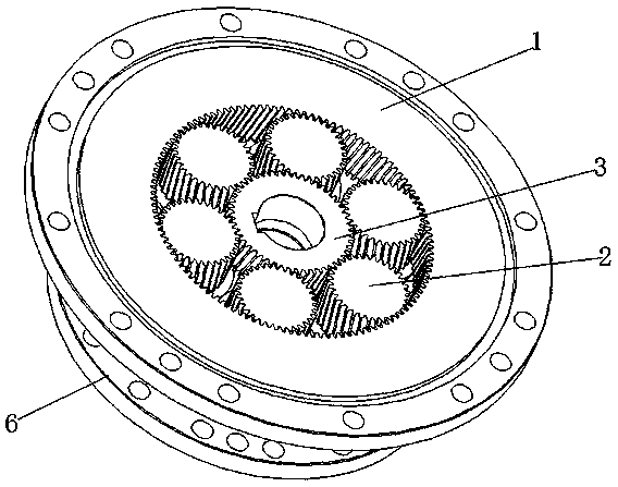
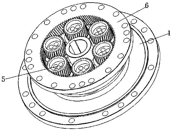
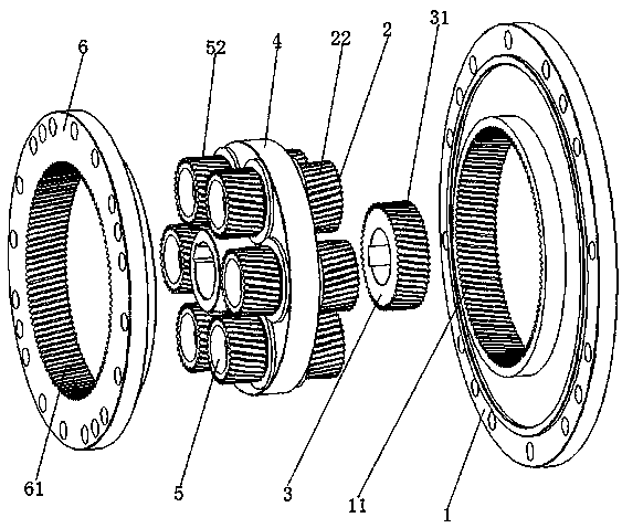
[0026] like Figure 1-4 As shown, a tooth difference planetary gear reducer includes a ring-shaped first-stage ring gear 1, and the upper end of the inner wall of the first-stage ring gear 1 is built with ring-shaped inner teeth 11 of the first-stage ring gear. The internal teeth 11 of the ring gear are meshed with at least two first-stage gears 2 arranged in a circle and in a convex shape, and the input gear 3 is meshed between the two first-stage gears 2, and the upper end of the first-stage gear 2 is fitted with a The first-stage bearing 21, and the first-stage bearing 21 is set in the circular input shaft 4, the upper end of the input shaft 4 is provided with a bearing hole 41 corresponding to the first-stage gear 2 and arranged in a circle, and the first-stage bearing 21 Set in the bearing hole 41, the bearing hole 41 is located at the other end of the set of primary bearing ...


PUM


Abstract

The invention discloses a gear differential planetary gear reducer. The gear differential planetary gear reducer comprises a first-stage gear ring, wherein inner teeth of the first-stage gear ring arearranged at the upper end of the inner wall of the first-stage gear ring, at least two first-stage gears which are arranged in a circular shape are meshed with the inner teeth of the first-stage gearring, and the middle of the two first-stage gears is meshed with an input gear; the upper end of each first-stage gear is sleeved with a first-stage bearing, and each first-stage bearing is arrangedin an input shaft in a sleeved mode; bearing holes matched with the first-stage gears are arranged at the upper end of the input shaft, the other ends, without sleeved with the first-stage bearings, of the bearing holes are connected to second-stage gears, and a second-stage bearing is connected to the upper end of each second-stage gear in a sleeved mode; and the second-stage bearings are sleevedin the bearing holes, the second-stage gears are meshed with second-stage gear rings, the upper end of the inner wall of each second-stage gear ring is provided with inner teeth of the second-stage gear ring, and the inner teeth of the second-stage gear ring are meshed with the second-stage gear ring. The gear differential planetary gear reducer has the advantages of being novel in design, simplein structure, free of friction balance transmission, simple in process, high in output power, high in impact resistance, large in speed reduction ratio range and the like.

Description

technical field [0001] The invention relates to the technical field of gear reducers, in particular to a planetary gear reducer with tooth difference. Background technique [0002] The existing reducers mainly include: planetary reducer, worm gear reducer, cycloid reducer and harmonic reducer. The planetary gear reducer has a small reduction ratio range, the worm gear reducer is a surface contact friction transmission, the friction transmission speed is limited (not exceeding 1500r / min), and the reduction ratio range is not large; the cycloidal gear reducer is a surface contact multi-teeth meshing without friction Transmission, high transmission precision, durable, but its crankshaft structure is an unbalanced movement that is prone to vibration, and the output is a pinhole clearance fit connection that is not compact and impact-resistant; the RV type cycloidal gear reducer is a multi-swing disc and multi-crankshaft type. Balanced motion, compact structure, strong impact re...

Claims


Application Information

Patent Timeline
IPC IPC(8): F16H1/32F16H57/023
CPCF16H1/32F16H57/023F16H2001/327F16H2001/289
Inventor 黄亮胡松林
Owner 广东大市智能装备有限公司
Features
  • R&D
  • Intellectual Property
  • Life Sciences
  • Materials
  • Tech Scout
  • Unparalleled Data Quality
  • Higher Quality Content
  • 60% Fewer Hallucinations
Learn More