
MEMS scanning mirror

A scanning mirror and mirror body technology, applied in the field of MEMS scanning mirrors, can solve the problems of height difference of comb teeth, high cost, unfavorable mass production, etc., and achieve the effect of reducing cost

Inactive Publication Date: 2019-11-26
SAIC MOTOR +1
View PDF22 Cites 3 Cited by
  • Summary
  • Abstract
  • Description
  • Claims
  • Application Information

AI Technical Summary

Problems solved by technology

[0005] The existing vertical comb structure has high cost when obtaining comb height difference, which is not conducive to mass production

Method used


Image

  • MEMS scanning mirror
  • MEMS scanning mirror
  • MEMS scanning mirror

Examples


Embodiment Construction

[0027] In view of this, the core of the present invention is to provide a MEMS scanning mirror to reduce costs.

[0028] In order to enable those skilled in the art to better understand the solution of the present invention, the present invention will be further described in detail below in conjunction with the accompanying drawings and specific embodiments.

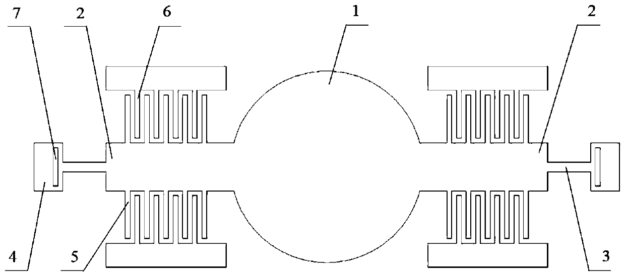
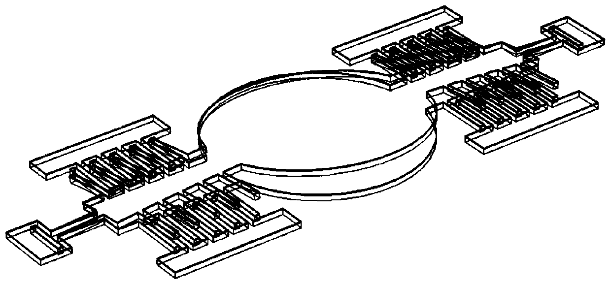
[0029] Such as Figure 1-Figure 3 As shown, the present invention discloses a MEMS scanning mirror, which includes: a mirror body 1 , a stress-bending beam 2 , a movable comb 5 , a fixed comb 6 and a torsion beam 3 . Among them, the stress bending beam 2 can be bent, and one end is connected to the mirror body 1 and the other end is connected to the torsion beam 3. The residual stress of the stress bending beam 2 shrinks from the top layer to the bottom layer along the thickness direction, so as to realize that the stress bending beam 2 warps when it is stressed. Both sides of mirror body 1 are provided with stress bend...


PUM


Abstract

The invention discloses an MEMS scanning mirror, which comprises a mirror body, movable comb teeth, fixed comb teeth and twist beams. The two sides of the mirror body are respectively connected with abendable stress bending beam, and the residual stress of each stress bending beam shrinks from the top layer to the bottom layer in the thickness direction; the movable comb teeth are arranged at theside surfaces of the stress bending beams; one end of each fixed comb tooth is fixed, and the other end is spaced with the stress bending beam; one end of each twist beam is connected with the otherend of the stress bending beam, and the other end of the twist beam is connected to a fixation member. Stress mismatch caused by the residual stress in the processing technology is used to make the stress bending beams warp and deform to drive the movable comb teeth to spontaneously produce height difference with the fixed comb teeth; since the residual stress is unavoidable in micro-nano processing technology and always exists more or less, realization of vertical comb teeth based on the residual stress does not require additional processing methods, and cost is reduced; and the MEMS scanningmirror has the advantages of self assembly and self alignment and the like.

Description

technical field [0001] The invention relates to the technical field of micro-opto-electromechanical systems, in particular to a MEMS scanning mirror. Background technique [0002] The MEMS (Micro-Electro-Mechanical System) scanning mirror based on micro-opto-mechanical system technology can realize precise control and positioning of the (laser) beam direction, and also has the advantages of small size, high speed, and low cost, so it is used in projection display , laser radar, laser processing, free space optical communication and many other aspects have broad application prospects. [0003] In terms of scanning methods, MEMS scanning mirrors can be divided into resonant scanning and quasi-static scanning. Compared with the resonant type, the quasi-static type has the advantages of low frequency requirement, wide application range, and simple control algorithm. [0004] Among them, the MEMS vertical comb driver is a mainstream driving method to realize quasi-static scanni...

Claims


Application Information

Patent Timeline
IPC IPC(8): G02B26/08G02B26/10
CPCG02B26/0833G02B26/10
Inventor 沙华露汪为民冯奇王强宁文果王锦楚延鹏李加鑫高咏王帅李智星
Owner SAIC MOTOR
Learn More