Automatic processing equipment of wiring terminal

A technology for automatic processing and terminal blocks, applied in metal processing equipment, assembly/disassembly of contacts, manufacturing tools, etc., can solve problems such as difficulty in judging the plastic case of terminal blocks, unstable assembly quality of terminal blocks, and high labor intensity

Inactive Publication Date: 2019-11-26
云和县宏峰模具厂
View PDF0 Cites 5 Cited by
  • Summary
  • Abstract
  • Description
  • Claims
  • Application Information

AI Technical Summary

Problems solved by technology

[0002] In the prior art, for the convenience of tap wiring of the transformer coil, the terminal is usually clamped on the mounting plate of the transformer bracket. The transformer terminal has three styles: single hole, double hole and three holes, and one of the terminals is made of plastic Shell, lugs and crimping screws. The lugs are clamped on the plastic case. The crimping screws are in contact with the lugs and are detachably set on the plastic case. In actual production, the wiring terminals need to manually connect the lugs and crimping Screws are installed separately, labor intensity is high, production cost is high, and the assembly quality of terminal blocks is unstable. The existing automation equipment cannot automatically assemble transformer terminal blocks, and it is difficult to judge unqualified terminal plastic cases during assembly, which affects production. efficiency, therefore, we propose an automatic processing equipment for terminal blocks in order to solve the problems raised above

Method used


Image

  • Automatic processing equipment of wiring terminal
  • Automatic processing equipment of wiring terminal
  • Automatic processing equipment of wiring terminal

Examples


Embodiment Construction

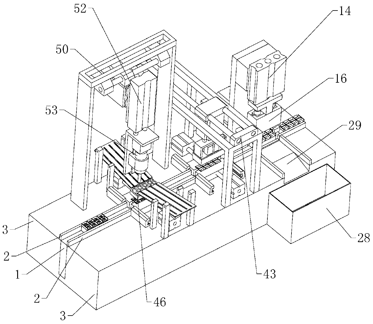
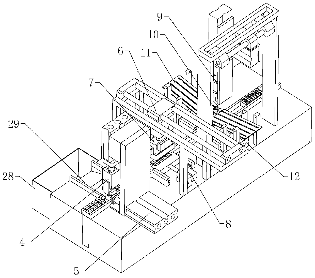
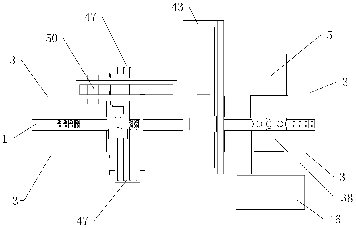
[0029] The technical solutions of the present invention will be further described below in conjunction with the accompanying drawings and through specific implementation methods.

[0030] Wherein, the accompanying drawings are only for illustrative purposes, showing only schematic diagrams, rather than physical drawings, and should not be construed as limitations on this patent; in order to better illustrate the embodiments of the present invention, some parts of the accompanying drawings will be omitted, Enlargement or reduction does not represent the size of the actual product; for those skilled in the art, it is understandable that certain known structures and their descriptions in the drawings may be omitted.

[0031] In the drawings of the embodiments of the present invention, the same or similar symbols correspond to the same or similar components; , "inner", "outer" and other indicated orientations or positional relationships are based on the orientations or positional ...


PUM


Abstract

The invention relates to the technical field of the wiring terminal processing, and specifically relates to automatic processing equipment of a wiring terminal. The automatic processing equipment comprises a plastic case feeding mechanism, a detection mechanism, a blade terminal feeding mechanism and a crimping screw feeding mechanism; the plastic case feeding mechanism comprises a tool track; thetool track comprises a feeding port and a discharging port; baffle plates are arranged at two sides of the tool track, and worktables are further arranged at two sides of the tool track; the detection mechanism comprises a hole site detection module and a waste pushout module; the blade terminal feeding mechanism comprises a blade terminal loading module, a blade terminal discharging module and two first positioning modules; the crimping screw feeding mechanism comprises a screw locking module, a positioning bush module, two screw feeding modules and two second positioning modules. The equipment can automatically tool the wiring terminal, the unqualified plastic case detected in the production can be automatically classified, and the production efficiency is improved.

Description

technical field [0001] The invention relates to the technical field of terminal processing, in particular to automatic processing equipment for terminal blocks. Background technique [0002] In the prior art, for the convenience of tap wiring of the transformer coil, the terminal is usually clamped on the mounting plate of the transformer bracket. The transformer terminal has three styles: single hole, double hole and three holes, and one of the terminals is made of plastic Shell, lugs and crimping screws. The lugs are clamped on the plastic case. The crimping screws are in contact with the lugs and are detachably set on the plastic case. In actual production, the wiring terminals need to manually connect the lugs and crimping Screws are installed separately, labor intensity is high, production cost is high, and the assembly quality of terminal blocks is unstable. The existing automation equipment cannot automatically assemble transformer terminal blocks, and it is difficult...

Claims


Application Information

Patent Timeline
IPC IPC(8): H01R43/20B23P21/00
CPCB23P21/004H01R43/20
Inventor 林迺建
Owner 云和县宏峰模具厂
Why Eureka
Try Eureka