Upwarp-preventing drilling equipment for guide rail production

A kind of drilling equipment and anti-warping technology, which is applied in the direction of drilling/drilling equipment, boring/drilling, metal processing equipment, etc., and can solve the problems of space occupation, long length of guide rail drilling device, and increased cost

Active Publication Date: 2020-02-18
佛山市顺德区海亮五金电器有限公司
View PDF5 Cites 4 Cited by
  • Summary
  • Abstract
  • Description
  • Claims
  • Application Information

AI Technical Summary

Problems solved by technology

Guide rails, also known as slide rails, linear guide rails, and linear slide rails, are used in linear reciprocating motion applications. They have a higher rated load than linear bearings, and can bear a certain torque at the same time. They can achieve high-precision linear motion under high load conditions. , the guide rail often needs to be drilled during production and processing, so as to facilitate the fixed installation of the guide rail when it is used. The length of the guide rail is basically five meters in the initial processing. When the hole device is drilling, due to the long length of the guide rail, in order to prevent one end of the guide rail from being lifted when it enters the device, it is necessary to set a longer platform for the length of the guide rail for feeding, thus resulting in a longer length of the guide rail drilling device , increase the cost, thereby occupying space, therefore, we propose a kind of anti-warping drilling equipment for guide rail production, in order to solve the problems raised above

Method used


Image

  • Upwarp-preventing drilling equipment for guide rail production
  • Upwarp-preventing drilling equipment for guide rail production
  • Upwarp-preventing drilling equipment for guide rail production

Examples


Embodiment Construction

[0025] The technical solution of the present invention will be further described below in conjunction with the accompanying drawings and through specific implementation methods.

[0026] Wherein, the accompanying drawings are only for illustrative purposes, showing only schematic diagrams, rather than physical drawings, and should not be construed as limitations on this patent; in order to better illustrate the embodiments of the present invention, some parts of the accompanying drawings will be omitted, Enlargement or reduction does not represent the size of the actual product; for those skilled in the art, it is understandable that certain known structures and their descriptions in the drawings may be omitted.

[0027]In the drawings of the embodiments of the present invention, the same or similar symbols correspond to the same or similar components; , "inner", "outer" and other indicated orientations or positional relationships are based on the orientations or positional re...


PUM


Abstract

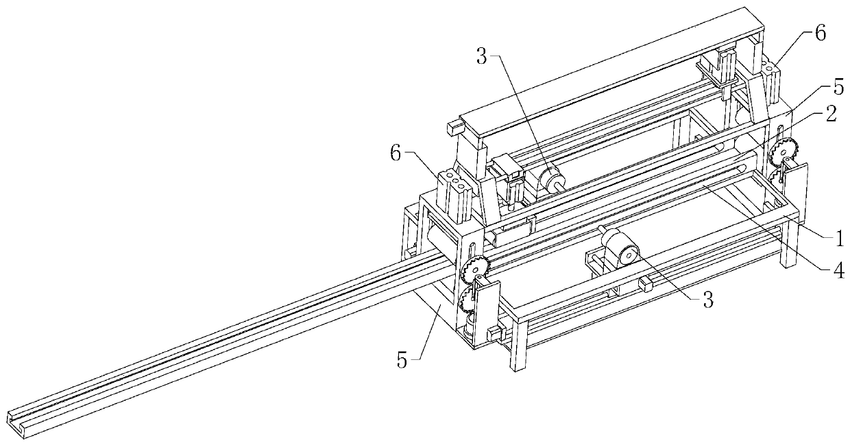
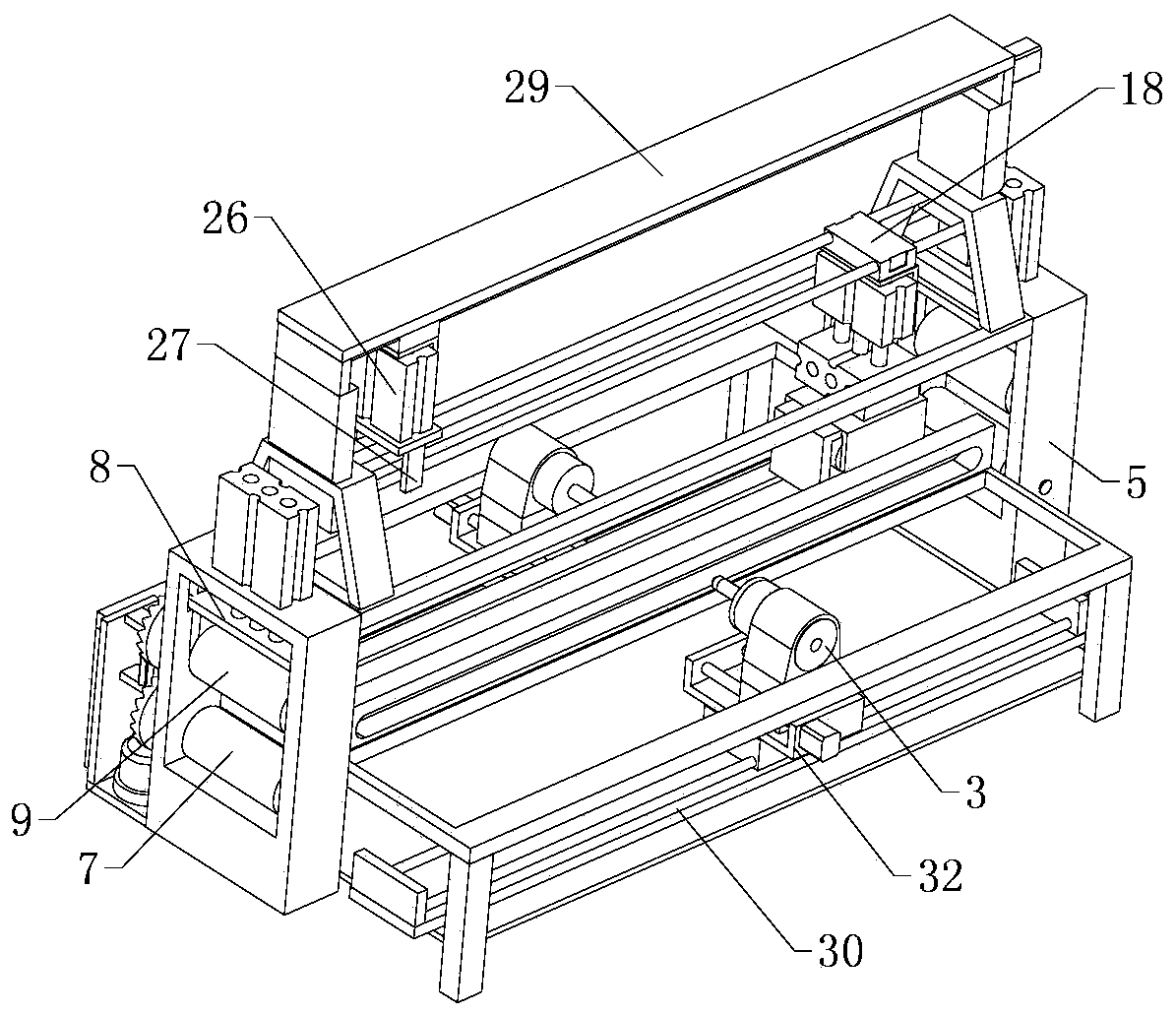
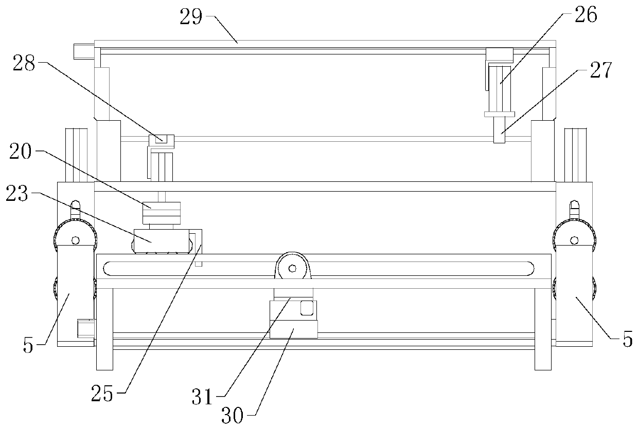
The invention relates to the technical field of guide rail processing, in particular to upwarp-preventing drilling equipment for guide rail production. The upwarp-preventing drilling equipment for guide rail production comprises a processing table. A horizontally arranged feeding track is arranged on the processing table; extension and retraction assemblies are separately arranged at two ends of the processing table; an upwarp-preventing assembly is arranged above the feeding track; the upwarp-preventing assembly comprises au upwarp-preventing guiding part capable of being in contact with topof a guide rail; a horizontal moving assembly is arranged above the upwarp-preventing assembly; a driving and clamping assembly is arranged at a working end of the horizontal moving assembly; drillingassemblies are separately arranged on two sides of the feeding track; a horizontal stepping assembly is arranged below each drilling machine; and each drilling assembly comprises the drilling machine; and rectangular notches where the drilling machines penetrate are separately formed in two sides of the feeding track. According to the equipment, when the guide rail is processed, the end, which iseasy to upwarp, of the guide rail is prevented from upwarping during feeding and discharging, so that the size of the equipment is reduced and the cost of the equipment is lowered.

Description

technical field [0001] The invention relates to the technical field of guide rail processing, in particular to an anti-warping drilling device for guide rail production. Background technique [0002] A guide rail is a groove or ridge made of metal or other materials that can bear, fix, guide a moving device or equipment and reduce its friction. Longitudinal grooves or ridges on the surface of rails for guiding and fixing machine parts, special equipment, instruments, etc. Guide rails, also known as slide rails, linear guide rails, and linear slide rails, are used in linear reciprocating motion applications. They have a higher rated load than linear bearings, and can bear a certain torque at the same time. They can achieve high-precision linear motion under high load conditions. , the guide rail often needs to be drilled during production and processing, so as to facilitate the fixed installation of the guide rail when it is used. The length of the guide rail is basically fi...

Claims


Application Information

Patent Timeline
Patent Type & Authority Applications(China)
IPC IPC(8): B23B41/00B23B47/00B23Q3/18
CPCB23B41/00B23B47/00B23Q3/18
Inventor 江德泉
Owner 佛山市顺德区海亮五金电器有限公司
Why Eureka
Try Eureka