Electromechanical integrated blender

The technology of a mixer and a mixing mechanism is applied in the direction of cement mixing devices, chemical instruments and methods, clay preparation devices, etc. It can solve the problems that the materials to be mixed cannot be turned up and down, and the mixing effect is poor, so as to achieve a good mixing effect and maintain a stable effect

Inactive Publication Date: 2020-07-10
于波
View PDF0 Cites 4 Cited by
  • Summary
  • Abstract
  • Description
  • Claims
  • Application Information

AI Technical Summary

Problems solved by technology

However, the stirring mechanisms used in the current mechatronic mixers are all rotating in the horizontal direction to achieve stirring, and the materials to be stirred cannot be turned up and down at the same time, and the stirring effect is poor.

Method used


Image

  • Electromechanical integrated blender
  • Electromechanical integrated blender
  • Electromechanical integrated blender

Examples


Embodiment 1

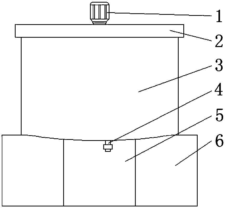
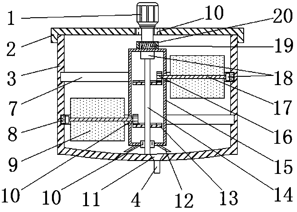
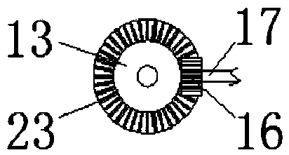
[0025] like figure 1 The shown mechatronic mixer includes a base 6 and a main cylinder 3 fixedly erected on the base 6. The upper end surface of the main cylinder 3 is open and is provided with a cover 2. The main cylinder 3 There is a stirring mechanism inside; such as figure 2 As shown, the stirring mechanism includes a rotating cylinder 15 vertically arranged in the middle of the main cylinder 3, and at least two stirring shafts 17 horizontally connected to the rotating cylinder 15 (two stirring shafts 17 are shown in the figure). , and the two stirring shafts 17 are respectively located in the upper and lower parts of the main cylinder 3) and the stirring blades 9 fixed on the stirring shaft 17, the rotating cylinder 15 is connected to the motor 1, and the output shaft of the motor 1 is vertical Arrangement, one end of the stirring shaft 17 penetrates the inside of the rotating cylinder 15 and is fixedly connected with the gear 16, and the inner bottom center of the main...

Embodiment 2

[0029] The difference between this embodiment and Embodiment 1 is:

[0030] In this embodiment, as figure 2 As shown, the motor 1 is installed at the top center of the cover body 2, and the output shaft of the motor 1 penetrates the cover body 2 and is connected with an outer active sleeve 20 in the shape of a groove with an opening downward. The top is fixed with an inner passive block 19 located inside the outer active sleeve 20, such as Figure 4As shown, the peripheral side of the inner passive block 19 is circular and is evenly provided with inner locking teeth 22, and the inner side surface of the outer active sleeve 20 is circular and is provided with outer locking teeth that engage with the inner locking teeth 22. 21. A sealed bearing 10 is provided on the cover body 2 at the position where the output shaft of the electric motor 1 passes through. When the cover body 2 is closed, the motor 1 realizes the transmission connection with the rotating cylinder 15 through t...

Embodiment 3

[0034] The difference between this embodiment and Embodiment 1 is:

[0035] In this embodiment, as Figure 5 As shown in the figure, scrapers for cleaning the annular chute 7 are fixed on both sides of the slider 8 corresponding to its moving direction, and the upper and lower ends of one side are respectively fixed with the upper and lower ends of the annular chute 7. The end surface scraper 24 for cleaning the end surface and the side scraper 25 for cleaning the side surface of the annular chute 7 are fixed at the rear end of the other side surface. The motor 1 is a forward and reverse rotation motor. When the motor 1 is rotating forward, the end scraper 24 moves with the movement of the slider 8, which can clean the upper and lower end surfaces of the annular chute 7; when the motor 1 is reversed, the side scraper 25 moves with the movement of the slider 8. By moving, the side surface of the annular chute 7 can be cleaned, thereby preventing materials from adhering to the ...


PUM


Abstract

The invention discloses an electromechanical integrated blender, and belongs to the technical filed of blenders. The electromechanical integrated blender comprises a base and a main cylinder body fixedly erected on the base, the main cylinder body is internally provided with a blending mechanism, the blending mechanism comprises a rotating cylinder body vertically arranged in the main cylinder body, at least two blending shafts horizontally connected to the rotating cylinder body and blending blades fixed to the blending shafts, the rotating cylinder body is driven by a motor to rotate in thehorizontal direction, one ends of the blending shafts penetrate into the inner side of the rotating cylinder body and are connected with gears, fixed discs which are horizontally arranged are arrangedon the lower parts of the gears, and annular gear rings engaged with the gears are arranged on the fixed discs; and the ends, facing backwards the gears, of the blending shafts are connected with sliding blocks which are slidably connected with the inner side wall of the main cylinder body through bearings, and annular sliding grooves corresponding to the fixed discs one by one and for corresponding sliding blocks to horizontally slide are formed in the inner side wall of the main cylinder body. According to the electromechanical integrated blender, the blending in the horizontal direction and up-down stirring of materials can be simultaneously achieved, the blending effect is good, and the operation stability is good.

Description

technical field [0001] The invention relates to the technical field of mixers, in particular to an electromechanical integration mixer. Background technique [0002] Mixer is a kind of construction engineering machinery, mainly used for mixing cement, sand, all kinds of dry mortar and other building materials. This is a machine in which a shaft with blades rotates in a cylinder or tank to agitate and mix various raw materials into a mixture or a suitable consistency. With the rapid development of science and technology, mechatronic mixers have been widely used. However, the stirring mechanisms used in the current mechatronic mixers are all rotated in the horizontal direction to achieve stirring, and the materials to be stirred cannot be turned up and down at the same time, and the stirring effect is poor. SUMMARY OF THE INVENTION [0003] 1. Technical problems to be solved [0004] The technical problem to be solved by the present invention is to provide an electromecha...

Claims


Application Information

Patent Timeline
Patent Type & Authority Applications(China)
IPC IPC(8): B28C5/08B28C5/14B28C5/16B28C7/04B28C7/16
CPCB28C5/0806B28C5/146B28C5/16B28C7/04B28C7/16
Inventor 于波周鹏屈东坡
Owner 于波
Why Eureka
Try Eureka