Dynamic phase noise compensation method and circuit for miniaturized phase-locked frequency source circuit

A dynamic phase and noise compensation technology, which is applied in the automatic control of power, electrical components, etc., can solve the problems of phase noise deterioration, and achieve the effects of reduced phase noise deterioration, fast response speed, and accurate compensation

Active Publication Date: 2019-11-26
SOUTHWEST CHINA RES INST OF ELECTRONICS EQUIP
View PDF6 Cites 7 Cited by
  • Summary
  • Abstract
  • Description
  • Claims
  • Application Information

AI Technical Summary

Problems solved by technology

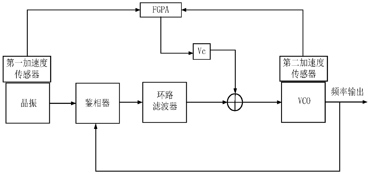
[0003] The present invention aims at the problem of phase noise deterioration under the condition of miniaturized phase-locked frequency source vibration, and provides a dynamic phase noise compensation method and method for miniaturized phase-locked frequency source circuit circuit

Method used


Image

  • Dynamic phase noise compensation method and circuit for miniaturized phase-locked frequency source circuit
  • Dynamic phase noise compensation method and circuit for miniaturized phase-locked frequency source circuit
  • Dynamic phase noise compensation method and circuit for miniaturized phase-locked frequency source circuit

Examples


Embodiment Construction

[0060] In order to make the objectives, technical solutions and advantages of the present invention clearer, the present invention will be further described in detail below with reference to the accompanying drawings and embodiments. It should be understood that the specific embodiments described herein are only used to explain the present invention, but not to limit the present invention, that is, the described embodiments are only a part of the embodiments of the present invention, rather than all the embodiments. The components of the embodiments of the invention generally described and illustrated in the drawings herein may be arranged and designed in a variety of different configurations. Thus, the following detailed description of the embodiments of the invention provided in the accompanying drawings is not intended to limit the scope of the invention as claimed, but is merely representative of selected embodiments of the invention. Based on the embodiments of the presen...


PUM


Abstract

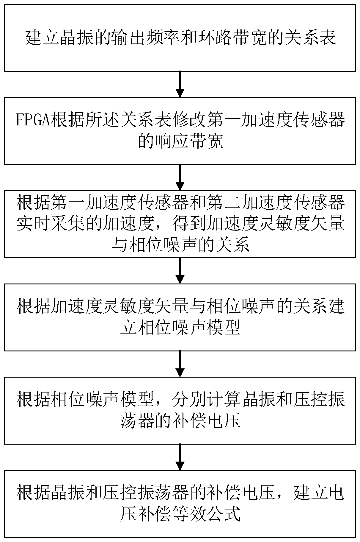
The invention discloses a dynamic phase noise compensation method and circuit for a miniaturized phase-locked frequency source circuit. The method comprises the following steps: step 1, establishing arelation table between the output frequency of a crystal oscillator and loop bandwidth; step 2, enabling an FPGA to modify the response bandwidth of a first acceleration sensor according to the relation table; step 3, according to accelerations collected by the first acceleration sensor and a second acceleration sensor in real time, obtaining a relationship between an acceleration sensitivity vector and phase noise; step 4, establishing a phase noise model according to the relationship between the acceleration sensitivity vector and the phase noise; step 5, respectively calculating compensation voltage of a crystal oscillator and a voltage-controlled oscillator according to the phase noise model; and step 6, establishing a voltage compensation equivalent formula according to the compensation voltages of the crystal oscillator and the voltage-controlled oscillator. By reading the acceleration values of the crystal oscillator and the voltage-controlled oscillator in real time, a voltagecompensation equivalent formula is established, and the method has the advantages of being high in corresponding speed and accurate in compensation.

Description

technical field [0001] The invention relates to a phase-locked frequency source circuit, in particular to a dynamic phase noise compensation method and circuit for a miniaturized phase-locked frequency source circuit. Background technique [0002] With the continuous development of electronic technology, phase-locked frequency sources, as frequency reference sources, are widely used in radar, navigation, communications and other equipment. As the "heart" of electronic equipment, its application environment has gradually expanded from static platforms to dynamic platforms such as satellites, missiles, and fighter jets. The frequency source system consists of a quartz crystal oscillator, a phase-locked loop, a VCO, and a loop filter. Among them, the quartz crystal oscillator is an acceleration sensitive device, and the oscillation frequency of the crystal will be unstable under the acceleration environment. In a dynamic environment, the phase-locked source will be affected b...

Claims


Application Information

Patent Timeline
Patent Type & Authority Applications(China)
IPC IPC(8): H03L7/08H03L7/087H03L7/099H03L7/16
CPCH03L7/0802H03L7/087H03L7/099H03L7/16
Inventor 吴穹冷国俊赖天华张文锋侯照临
Owner SOUTHWEST CHINA RES INST OF ELECTRONICS EQUIP
Why Eureka
Try Eureka