A training device for sit-ups
A technology of trainers and main poles, applied in gymnastics equipment, sports accessories, etc., can solve the problems of inability to adjust, troublesome operation, and no auxiliary devices, etc., to increase stability and bearing capacity, simple operation, and ensure stability Effect
- Summary
- Abstract
- Description
- Claims
- Application Information
AI Technical Summary
Problems solved by technology
Method used
Image
Examples
Embodiment 1
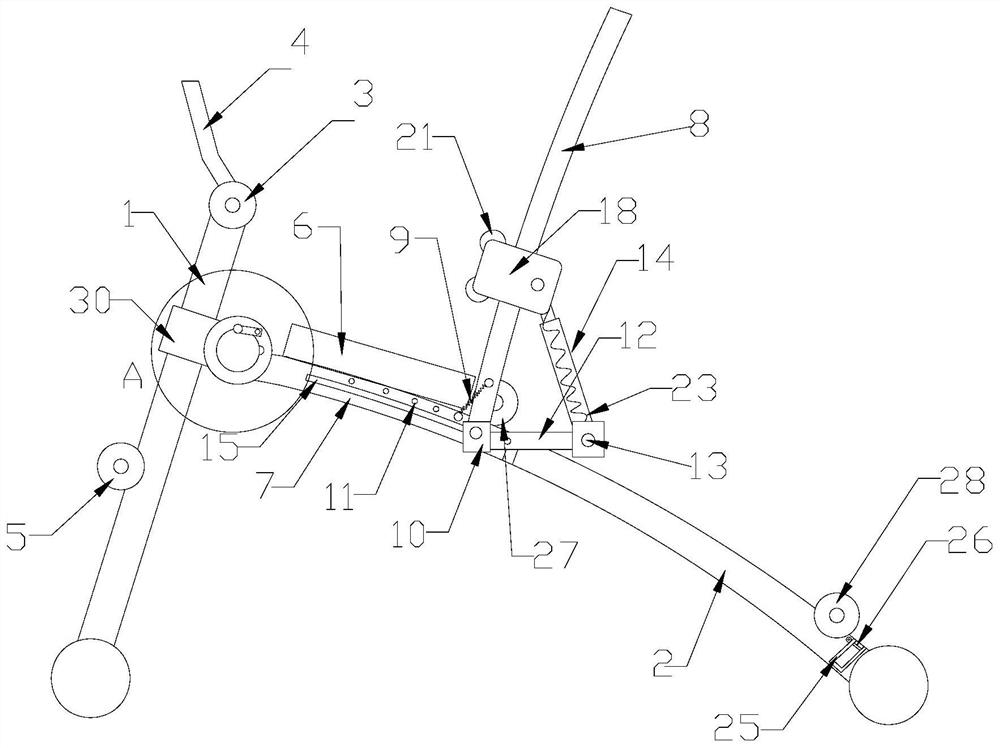
[0033] Such as figure 1 As shown, a sit-up trainer includes a front strut 1 and a main strut 2, the upper end of the front strut 1 is fixed with a buckle foot pad 3 by bolts, and the top end of the front strut 1 is fixed with a handle 4, The lower end of the front strut 1 is provided with a plurality of fixing holes from bottom to top, and the lower buckle foot pad 5 is fixedly connected with the front strut 1 by bolts passing through the fixing holes, and the height of the lower buckle foot pad 5 is adjusted through the fixing holes. Suitable for trainers of different heights. The top of the main pole 2 is foldably connected with the front pole 1, and the upper end of the main pole 2 is fixed with a cushion 6.
[0034]Both sides of main strut 2 upper ends are all fixed with guide bar 7, and guide bar 7 is provided with the auxiliary mechanism that is used to finish sit-ups, and auxiliary mechanism includes movable bar 8, first extension spring 9, slide bar assembly and reset...
Embodiment 2
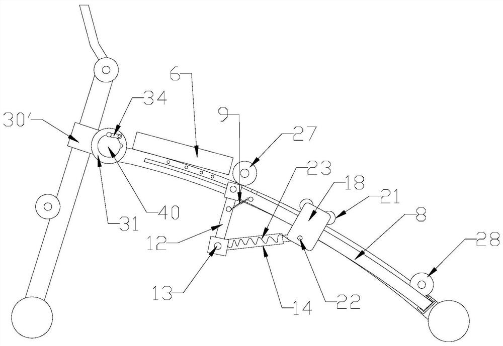
[0037] This embodiment is basically the same as Implementation 1, the difference is that: Figure 1-4 As shown in and 6, a bar-shaped guide sliding hole 15 is arranged in the axial direction on the guide rod 7, and the connecting seat 10 includes a connecting rod 16. One end of the connecting rod 16 is provided with an annular groove 17 hinged with the movable rod 8, and the other end passes through the The guide sliding hole 15 is fixedly connected with the guide rod 7 through a lock nut, the connecting hole 11 is arranged along the strip-shaped sliding hole, and the first extension spring 9 is fixedly connected with the connecting hole 11 through a bolt.
[0038] The sliding bar assembly includes sliding plates 18 positioned at both sides of the movable bar 8, the upper and lower ends of the sliding plate 18 are equipped with rollers 19 that move along the movable bar 8, and the both sides of the upper end of the sliding plate 18 are fixed with wheels towards the main pole 2....
Embodiment 3
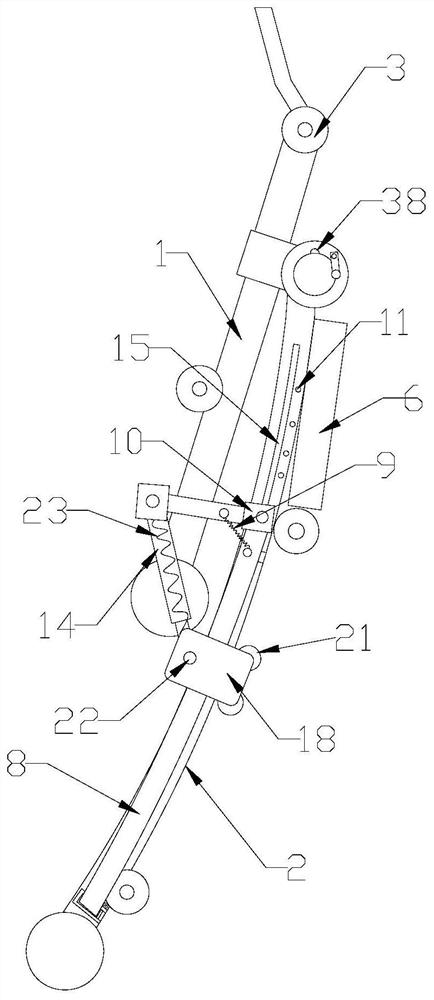
[0046] This embodiment is basically the same as Embodiment 2, the difference is: as Image 6 with 8 As shown, a plurality of through holes are arranged at intervals along the axial direction on the guide rod 7, and the connecting seat 10 includes a connecting rod 16. One end of the connecting rod 16 is provided with an annular groove 17 hinged with the movable rod 8, and the other end passes through the through hole. It is fixedly connected with the guide rod 7 through a lock nut, the connecting hole 11 is located above the side of the through hole close to the front pole 1, and the first extension spring 9 is fixedly connected with the connecting hole 11 by bolts.
[0047] Such as Figure 4 As shown, the end of the sliding rod body 20 close to the main rod 2 is equipped with a support wheel 29 rolling along the main rod 2 , and the movable rod 8 has the same bending arc as the main rod 2 . The support of the free end of the sliding rod body 20 by the main support rod 2 is u...
PUM
 Abstract
Description
Claims
Application Information
 - R&D
- Intellectual Property
- Life Sciences
- Materials
- Tech Scout
- Unparalleled Data Quality
- Higher Quality Content
- 60% Fewer Hallucinations
Browse by: Latest US Patents, China's latest patents, Technical Efficacy Thesaurus, Application Domain, Technology Topic, Popular Technical Reports.
© 2025 PatSnap. All rights reserved.Legal|Privacy policy|Modern Slavery Act Transparency Statement|Sitemap|About US| Contact US: help@patsnap.com


