

Cable tower beam installation support structure
A technology for supporting structures and beams, used in bridges, bridge construction, bridge parts, etc., can solve the problems of low support strength of corbels, insufficient support strength, safety accidents, etc. The effect of force equalization
Active Publication Date: 2017-08-29
THE 3RD ENG CO LTD OF CHINA RAILWAY 16TH BUREAU GRP CO LTD
View PDF21 Cites 8 Cited by
- Summary
- Abstract
- Description
- Claims
- Application Information
AI Technical Summary
Problems solved by technology
There are also some structures that are supported by corbels. However, the existing corbels have low support strength and are easy to loosen. The support strength is not enough. In actual use, some brackets are still needed for auxiliary support.
Moreover, the existing corbels have low support strength and are easy to collapse. Once they collapse, there will be major safety accidents without safety protection.
Method used
View moreImage
Smart ImageViewing Examples


Examples
Embodiment 1
Embodiment 2
Embodiment 3
Login to View More PUM
| Property | Measurement | Unit |
|---|---|---|
| Diameter | aaaaa | aaaaa |
| Shear strength | aaaaa | aaaaa |
Abstract
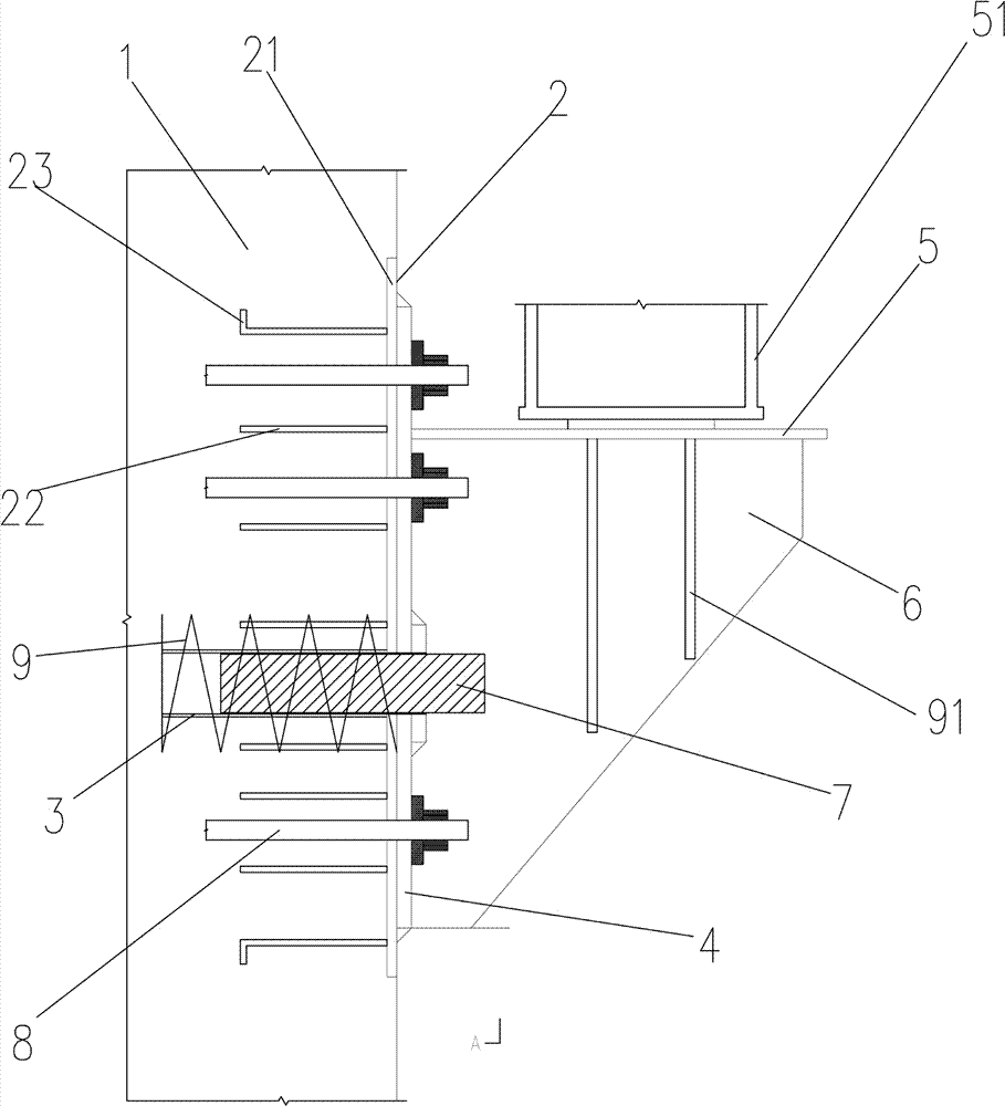
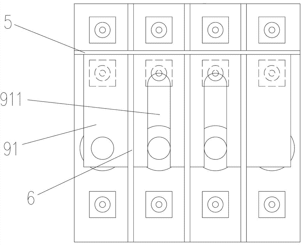
The invention belongs to the field of architecture, and particularly relates to a cable tower beam installation support structure. The structure comprises a pre-buried component which is pre-buried in a tower body of the cable tower, a support component which is in an abutting joint with the pre-buried component and arranged on the tower body, and a connection component which is used for fixedly connecting the support component and the pre-buried component; the pre-buried component comprises a pre-buried steel plate which is vertically arranged and pre-buried on the inner side face of the tower body and has an exposed installation surface, and a steel tube which is perpendicular to the inner side face of the tower body and the plate surface of the pre-buried steel plate and extends to the tower body; the support component comprises an installation baseplate which is clung to the pre-buried steel plate, a top plate which is perpendicular to and fixedly connected to the installation baseplate, and a plurality of stiffening ribs which are fixedly connected to the installation baseplate and a top support plate and are arranged in parallel, wherein the stiffening ribs, the installation baseplate and the top support plate are perpendicular to each other. According to the cable tower beam installation support structure, bearing steel bars and rectification steel bars with different diameters bear gravity which comes down from the top and force generated by offcenter respectively. Meanwhile, through a distribution beam of the top, reasonable distribution is conducted, the force transmitted to the top plate is more balanced and better in stability, and the installation and the assembly are more convenient.
Description
A cable tower beam installation support structure technical field The invention belongs to the field of construction, and in particular relates to a support structure for installing a cable tower beam. Background technique Due to the high height and weight of the beam on the cable tower, the existing method of construction is to use floor supports and construction supports to support and then build the beam on it, and then remove the support after the beam is completed. This method consumes more materials. The amount of high-altitude assembly is relatively large, and the safety risk is relatively high. There are also some structures that are supported by corbels. However, the existing corbels have low support strength and are easy to loosen. The support strength is not enough. In actual use, some brackets are still needed for auxiliary support. And the existing corbel support strength is low, easy to collapse, once collapse will cause major safety accident without safety ...
Claims
Login to View More Application Information
Patent Timeline
 IPC IPC(8): E01D21/00E01D19/14
CPCE01D19/14E01D21/00Y02E10/72
Inventor王小飞霍二伦马晓旭马胜辉潘寿东卫鹏金仁贵
OwnerTHE 3RD ENG CO LTD OF CHINA RAILWAY 16TH BUREAU GRP CO LTD