Fixed length shearing machine for wire harnesses and wire cables of new energy automobile

A new energy vehicle, fixed-length cutting technology, applied in the field of wire harness processing, can solve the problems of easy slippage of the wire harness, easy occurrence of large errors, low cutting precision of the wire harness, etc., to improve the cutting effect and ensure the effect of smooth release.

Active Publication Date: 2019-11-29
博锐腾新能源科技(淮安)有限公司
View PDF6 Cites 7 Cited by
  • Summary
  • Abstract
  • Description
  • Claims
  • Application Information

AI Technical Summary

Problems solved by technology

[0004] 1. Manually measure the automotive wiring harness. The automotive wiring harness cannot be guaranteed to be in a tensioned state. Large errors are prone to occur during measurement, resulting in low cutting accuracy of the wiring harness. In this way, the cut wiring harness often needs to be cut twice when it is used. cutting, it consumes a lot of manpower and material resources, and the production efficiency is low;
[0005] 2. When the manual hand-held cutter machine is used to cut the wire harness, the worker often holds the wire harness to cut, which cannot be fixed and limited. When cutting, the wire harness is easy to slip away, cannot be cut at one time, and the cutting effect is poor

Method used


Image

  • Fixed length shearing machine for wire harnesses and wire cables of new energy automobile
  • Fixed length shearing machine for wire harnesses and wire cables of new energy automobile
  • Fixed length shearing machine for wire harnesses and wire cables of new energy automobile

Examples


Embodiment Construction

[0029] In order to make the technical means, creative features, goals and effects achieved by the present invention easy to understand, the present invention will be further described below in conjunction with specific illustrations. It should be noted that, in the case of no conflict, the embodiments in the present application and the features in the embodiments can be combined with each other.

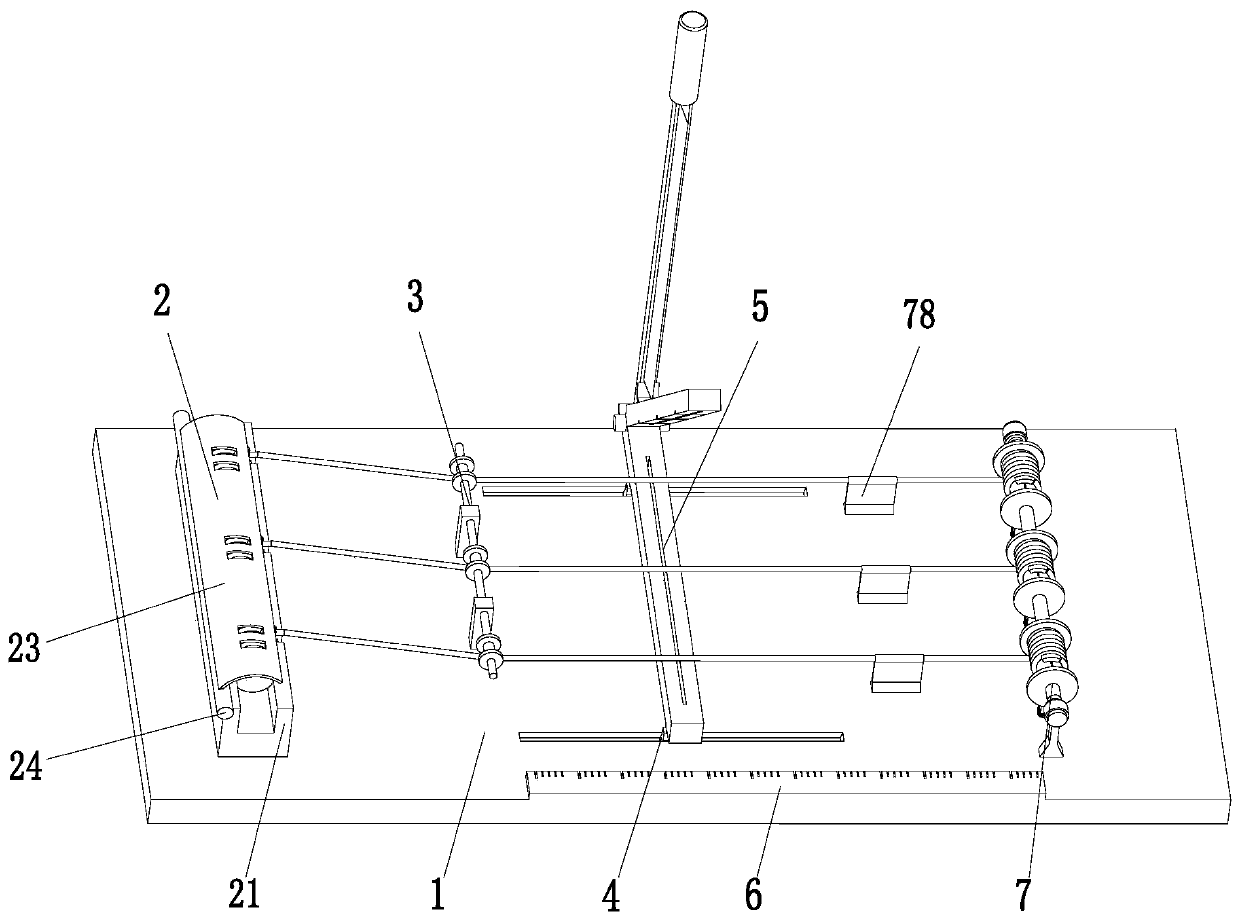
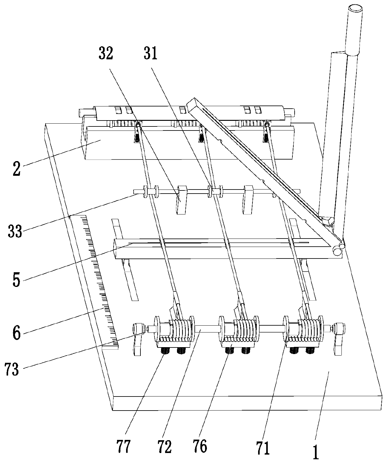
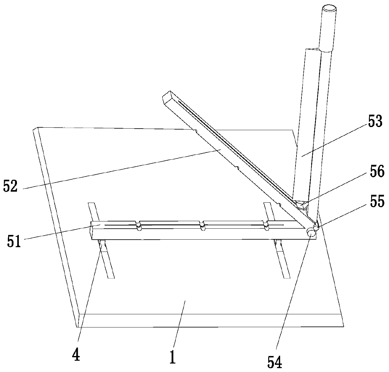
[0030] Such as Figure 1 to Figure 5 As shown, a new energy vehicle wire harness cable fixed-length cutting machine, including a base plate 1, a wire release mechanism 2, a limit mechanism 3, an electric slider 4, a cutting mechanism 5, a scale 6 and a fixed-length mechanism 7, The middle part of the top of the base plate 1 is symmetrically provided with chute front and rear, the top left side of the base plate 1 is equipped with a pay-off mechanism 2, the limit mechanism 3 is located on the right side of the pay-off mechanism 2, and the two ends of the limit mechanism 3 are installe...


PUM


Abstract

The invention relates to a fixed length shearing machine for wire harnesses and wire cables of a new energy automobile. The fixed length shearing machine comprises a bottom plate, a pay-off mechanism,a limiting mechanism, electric slide blocks, a shearing mechanism, a dividing rule and a fixed length mechanism. Chutes are symmetrically formed front and back in the middle part of the top end of the bottom plate, the pay-off mechanism is mounted on the left side of the top end of the bottom plate, the limiting mechanism is located on the right side of the pay-off mechanism, two ends of the limiting mechanism are mounted at the top end of the bottom plate, the electric slide blocks are connected in the chutes of the bottom plate in a sliding fit manner, the shearing mechanism is arranged onthe right side of the limiting mechanism, two ends of the shearing mechanism are mounted at the top ends of the electric slide blocks, the dividing rule is mounted on the front side of the middle partof the top end of the bottom plate, the fixed length mechanism is located on the right side of the shearing mechanism, and the fixed length mechanism is mounted on the right side of the top end of the bottom plate. The fixed length shearing machine can solve the problems that the shearing precision is low as the measuring length has a relatively large error when the wire harnesses are sheared manually, and the cutting effect is poor as a pair of cutting pliers is manually held to cut the wire harnesses and the like.

Description

technical field [0001] The invention relates to the field of wire harness processing, in particular to a new energy automobile wire harness cable fixed-length cutting machine. Background technique [0002] The automobile wiring harness is the main body of the automobile circuit network. Without the wiring harness, there will be no automobile circuit. The wiring harness refers to the contact terminal made of copper punched and crimped with the wire and cable, and the outside is molded with an insulator or a metal shell, etc. , to form components connecting circuits by bundling wire harnesses. The wire harness industry chain includes wires and cables, connectors, processing equipment, wire harness manufacturing and downstream application industries. Wire harnesses are widely used and can be used in automobiles, household appliances, computers and communication equipment, and various electronic products. Instrumentation etc. [0003] Automobile wiring harnesses often need to b...

Claims


Application Information

Patent Timeline
IPC IPC(8): B21F11/00B21F23/00B21C51/00
CPCB21C51/00B21F11/00B21F23/00
Inventor 赵青山李健
Owner 博锐腾新能源科技(淮安)有限公司
Why Eureka
Try Eureka