Al technical title is built by PatSnap Al team. It summarizes the technical point description of the patent document.
A jet nozzle, centralized technology, applied in the field of centralized rotating cavitation jet nozzle, can solve the problems of water jet energy concentration, energy non-concentration, low energy concentration of cavitation water jet, etc. Shear action, effect of improving erosion ability
Inactive Publication Date: 2015-01-28
XIHUA UNIV
View PDF7 Cites 14 Cited by
Summary
Abstract
Description
Claims
Application Information
AI Technical Summary
This helps you quickly interpret patents by identifying the three key elements:
Problems solved by technology
Method used
Benefits of technology
Problems solved by technology
However, in the application process, the existing cavitation water jet nozzles have many deficiencies, which are mainly manifested in: 1) The cavitation effect of the organ tube type cavitation jet nozzle used for cleaning is poor, and the outlet cavity cannot make the water jet energy Concentration, the energy concentration on the section of cavitation water jet is low; 2) The traditional cavitation water jet nozzle used for cutting and rock breaking has low jet beam velocity, non-concentrated energy and large action area, which is used for drilling, Poor effect and low efficiency when cutting and breaking rock
Method used
Image
Click on the blue label to locate the original text in one second.
Reading with bidirectional positioning of images and text.
Examples
Embodiment 1
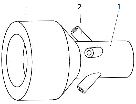
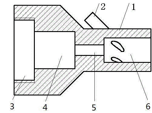
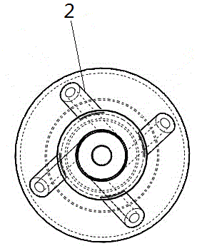
[0019] see figure 1 , figure 2 and image 3 , the centralized rotating cavitation jet nozzle is connected to the high-pressure water pipeline through the thread of the inlet section, and the inner flow channel of the nozzle consists of a cylindrical inlet section (3), a cylindrical resonant cavity (4), a cylindrical small hole (5) and a cylindrical outlet section (6), on the nozzle body (1) there are multiple inlet pipes (2) along the circumference, the inlet pipes (2) lead to compressed air, the inner hole of the inlet pipe (2) and the cylindrical outlet section (6 ) tangent to the inner hole, and the inner diameter of the air inlet pipe (2) is 1 / 2 of the difference between the inner diameter of the cylindrical outlet section (6) and the inner diameter of the cylindrical small hole (5).
[0020] see figure 2 , when water (or other fluid) enters from the cylindrical inlet section (3), it is ejected from the cylindrical hole (5) through the cylindrical resonant cavity (4) ...
PUM
Abstract
The invention relates to an integrated rotary cavitating jet nozzle comprising a cylindrical inlet segment, a cylindrical resonant cavity, a cylindrical pore and a cylindrical outlet segment. The cylindrical outlet segment is provided with a plurality of intake tubes; bores of the intake tubes are tangent to a bore of the cylindrical outlet segment. The inner diameter of the intake tubes is half a difference between the inner diameter of the cylindrical outlet segment and the diameter of the cylindrical pore. The section of the bore of each intake tube is round, square, or in any special shape. The intake tubes can be axially distributed in multiple rows at the cylindrical outlet segment of a nozzle body. Compressed air is led into the intake tubes, the compressed air led in from the intake tubes enters in the tangent direction, air swirls surrounding a water jet are formed in the cylindrical outlet segment and drive the water jet to turn into a rotating vortex in the cylindrical outlet segment, and cavitating effect is further enhanced; meanwhile, cavitating bubbles are concentrated to the center of the water jet, energy of the cavitating water jet is more concentrated, the shear action of the jet upon a target is enhanced, and eroding capacity of the cavitating jet is greatly improved accordingly.
Description
technical field [0001] The invention relates to a cavitation jet nozzle, in particular to a centralized rotating cavitation jet nozzle, which can be used for material surface cleaning, rust removal, degumming, surface strengthening, drilling, cutting, rock breaking and the like. Background technique [0002] Water jet special processing uses a water jet beam with high kinetic energy to erode materials, thereby realizing material cutting, which belongs to the category of high energy beam processing. Water jet processing belongs to non-contact "cold cutting", without mechanical stress, heat deformation, heat-affected zone, so it becomes the best cutting method for heat-sensitive materials; it has good adaptability, excellent cutting quality, narrow kerf, and less material loss , and the medium cost is low, clean, dust-free, non-toxic, and environmentally friendly during the cutting process, and is widely used in machinery manufacturing, aerospace, automotive, military, and cer...
Claims
Application Information
Patent Timeline
Application Date:The date an application was filed.
Publication Date:The date a patent or application was officially published.
First Publication Date:The earliest publication date of a patent with the same application number.
Issue Date:Publication date of the patent grant document.
PCT Entry Date:The Entry date of PCT National Phase.
Estimated Expiry Date:The statutory expiry date of a patent right according to the Patent Law, and it is the longest term of protection that the patent right can achieve without the termination of the patent right due to other reasons(Term extension factor has been taken into account ).
Invalid Date:Actual expiry date is based on effective date or publication date of legal transaction data of invalid patent.