
Stirring device and horizontal double-shaft self-cleaning reactor

A technology of stirring device and stirring plate, which is applied in mixers with rotating stirring devices, chemical/physical/physical-chemical stationary reactors, mixer accessories, etc. , heavy and other problems, to achieve the effect of enhanced shearing ability, good self-cleaning effect, and enhanced stirring and mixing effect

Active Publication Date: 2018-07-03
ZHEJIANG UNIV
View PDF5 Cites 13 Cited by
  • Summary
  • Abstract
  • Description
  • Claims
  • Application Information

AI Technical Summary

Problems solved by technology

This results in a bulky and heavy shaft, which severely limits the practical industrial application of twin-screw extruders

Method used


Image

  • Stirring device and horizontal double-shaft self-cleaning reactor
  • Stirring device and horizontal double-shaft self-cleaning reactor
  • Stirring device and horizontal double-shaft self-cleaning reactor

Examples


Embodiment 1

[0037] Example 1: Self-cleaning process of a biaxial reactor

[0038] The structure and principle of the reactor are as mentioned above, the ratio of the rotational speed of the two rotating shafts is 4:5, and the ratio of the supporting rods of the rotating shaft stirring plate is 5:4. Comparing the reactor described in Chinese patent (CN201210186362.5, 2012) with the horizontal double-shaft self-cleaning reactor with double-layer and three-layer stirring blades distributed radially, the stirring blades on the second rotating shaft are obtained Schematic diagram of the relative motion trajectory relative to the first rotation axis. Compared with the traditional single-layer horizontal double-shaft self-cleaning stirring reactor, the horizontal double-shaft self-cleaning reactor with radially distributed double-layer stirring blades has more blades and is distributed up and down in multiple layers. When rotating around the rotating shaft, it can self-clean the entire space of...

Embodiment 2

[0039] Embodiment 2: the final polycondensation process of poly-p-phenylene terephthalamide

[0040] In the later stage of the polymerization process of poly-p-phenylene terephthalamide, the viscosity of the reaction system is very high, and it is difficult for the traditional reactor to reach the product target. The structure and principle of the reactor are as described above, and the structural parameters of some reactors are as follows: the length of the stirring blades on the first rotating shaft and the second rotating shaft is 40-80 mm, and the stirring blades on the two shafts are arranged at intervals, and the distance between the stirring discs of the rotating shafts is 30 mm. -80mm, the distance between the stirring paddles distributed radially on the rotating shaft is 30-80mm. Due to the use of double-layer blades, when the two blades in the middle of the kettle intersect each other, the shear rate reaches the maximum, and the fluid in the flow field can experience...


PUM


Abstract

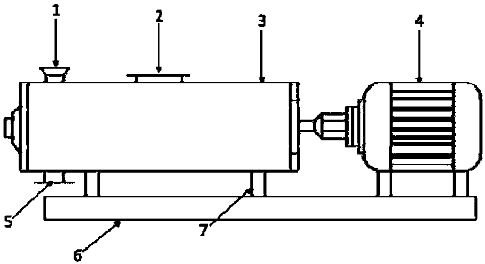
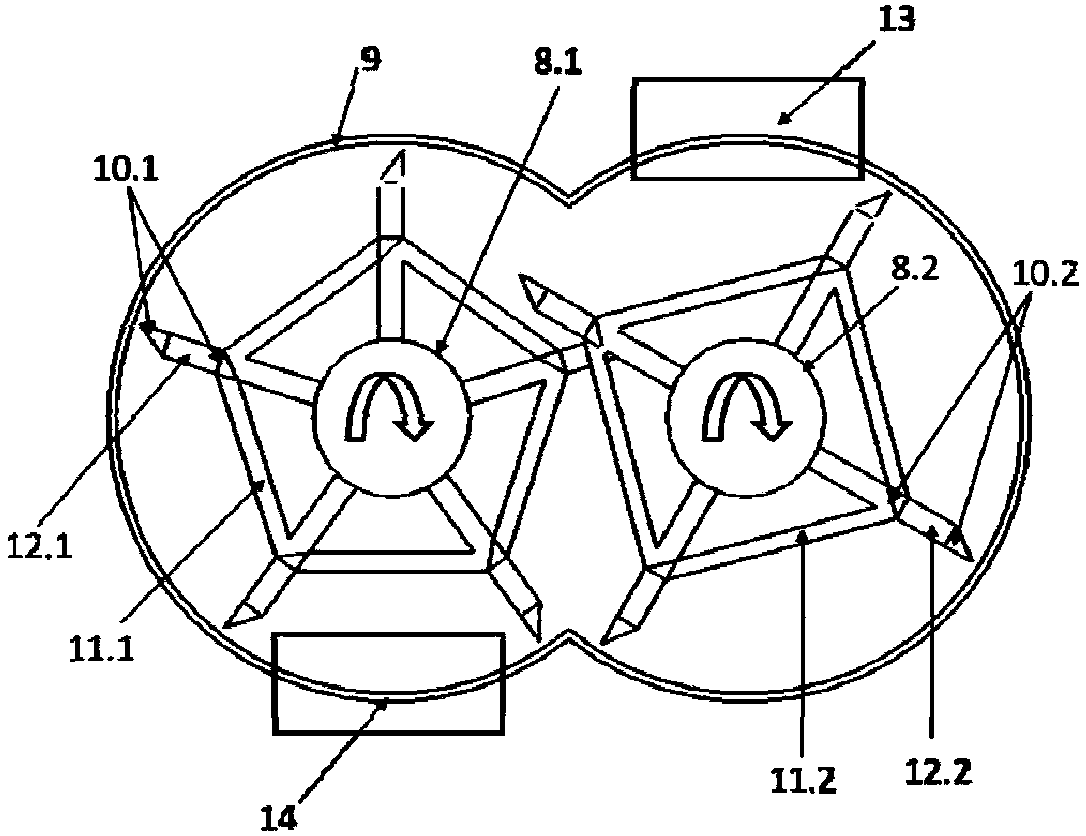
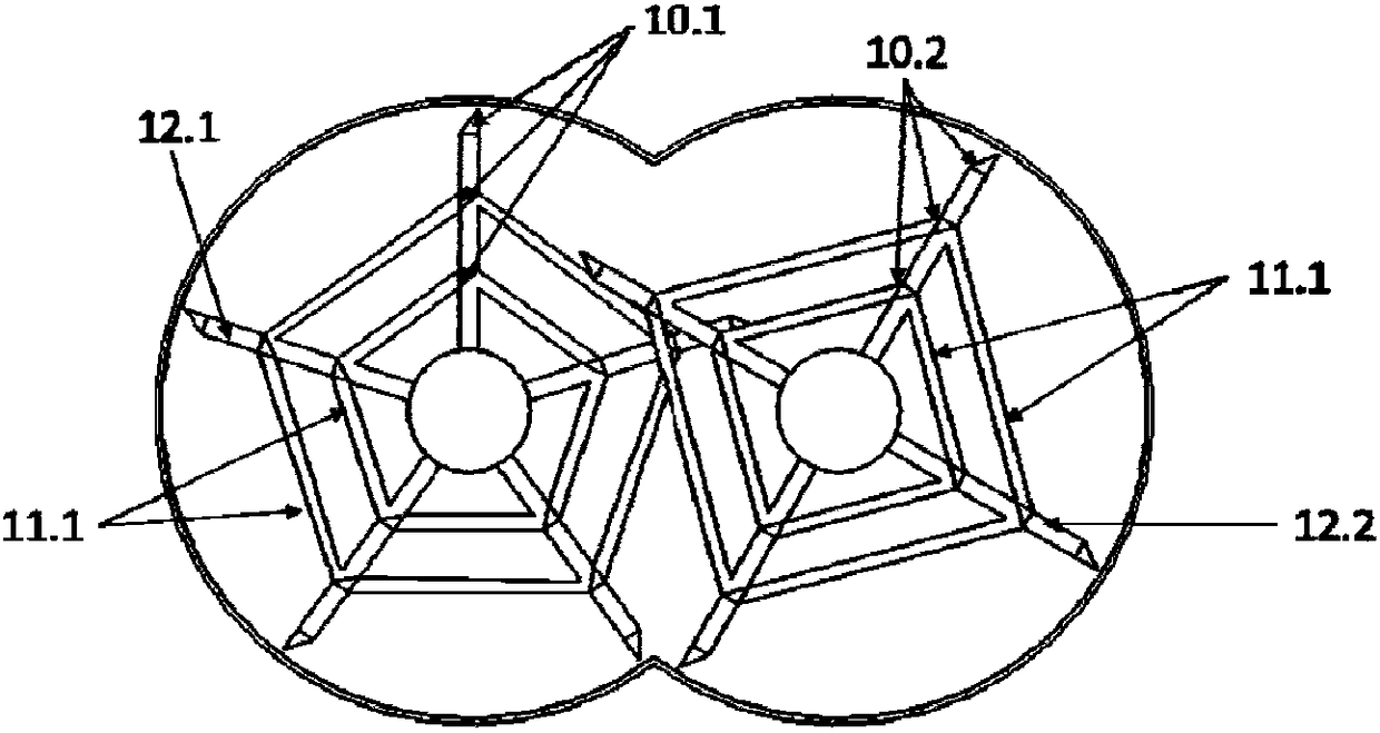
The invention relates to a stirring device which comprises two rotating shafts, wherein a plurality of same stirring discs are axially fixed to the rotating shaft; each stirring disc is composed of aplurality of same radially arranged stirring rods and a fixed rod connected to two adjacent stirring rods; each stirring rod comprises supporting rods arranged radially and two or more stirring bladesarranged on the supporting rods vertically, wherein one of the stirring blades is located at the tail end of the supporting rod, and the stirring discs on the two rotating shafts are arranged in a staggered manner. The invention also provides a horizontal double-shaft self-cleaning reactor based on the stirring device. Compared with a conventional horizontal double-shaft reactor, the horizontal double-shaft self-cleaning reactor is simple in structure, has a bigger reaction space, materials are sheared and stretched in a kettle body, so that the reactor is suitable for fluids with different viscosities; the standing time is controllable; compared with the conventional horizontal double-shaft reactor, full reaction regions in the kettle body scratch one another, so that the self-cleaning effect is good. The reaction energy consumption is low, and the mixing efficiency is high.

Description

technical field [0001] The invention relates to a stirring device and a horizontal biaxial self-cleaning reactor. Background technique [0002] For the high-viscosity polymerization reaction process, the viscosity of the system in the later stage of the reaction increases continuously with the progress of the reaction, with tens of milliPascal seconds and finally even hundreds of thousands of milliPascal seconds, at this time the flow of materials becomes extremely difficult For materials with high boiling point, especially heavy tar or phenol tar, coal tar, polymer and other similar materials with high viscosity, high freezing point and high heat sensitivity, foaming or puffing usually occurs at high temperature, and some also There may even be a phenomenon of rheological curing. For conventional stirred reactors, due to the high viscosity, high temperature and poor fluidity of the material, it is easy to agglomerate in the reactor body, forming a dead zone, causing carbon...

Claims


Application Information

Patent Timeline
Patent Type & Authority Applications(China)
IPC IPC(8): B01J19/18B01F7/10B01F15/00B01F27/73
CPCB01J19/0066B01J19/18B01F27/0722B01F27/091B01F27/074B01F27/171B01F27/421B01F27/2322B01F27/731B01F35/123
Inventor 叶阳王嘉骏成文凯顾雪萍冯连芳
Owner ZHEJIANG UNIV
Learn More