Integrated autotrophic synchronous biological denitrification granulation device

A biological denitrification, autotrophic technology, applied in biological treatment devices, biological water/sewage treatment, chemical instruments and methods, etc., can solve problems such as difficulty in forming high efficiency, long doubling time, and difficulty in sedimentation, and reduce application The effect of promotion difficulty, harsh growth conditions and good sedimentation performance

Active Publication Date: 2016-07-27
BIOGAS SCI RES INST MIN OF AGRI
View PDF7 Cites 14 Cited by
  • Summary
  • Abstract
  • Description
  • Claims
  • Application Information

AI Technical Summary

Problems solved by technology

The disadvantages of this process are: first, the process efficiency is low, 1.8kg-N / m3 / day
Second, because nitrite, nitrate and organic matter still remain in the effluent, it is easy to produce gas and bring up the sludge, making it difficult to settle
Third, the anaerobic ammonium oxidation granular sludge is used as the inoculated sludge, which has a long doubling time (11 days) and is difficult to obtain
The disadvantages of this patent are: first, the aerobic and anaerobic stages form a physical partition, which is prone to nitrite inhibition. Since the aerobic stage is an acidification process and the anaerobic stage is a simplified process, anaerobic bacteria need ammonia nitrogen: nitrite Nitrogen is close to about 1:1, so there are still problems that pH and ammonia nitrogen / nitrite nitrogen ratio are difficult to control, and it is difficult to form high-efficiency
Second, it is necessary to add a circulation pump to realize the circulation of waste water and increase energy consumption
Third, using anammox granular sludge as the inoculum, the inoculum is difficult to obtain

Method used


Image

  • Integrated autotrophic synchronous biological denitrification granulation device
  • Integrated autotrophic synchronous biological denitrification granulation device

Examples


Embodiment Construction

[0026] The implementation of the present invention will be described in detail below with examples, so as to fully understand and implement the implementation process of how the present invention uses technical means to solve technical problems and achieve technical effects.

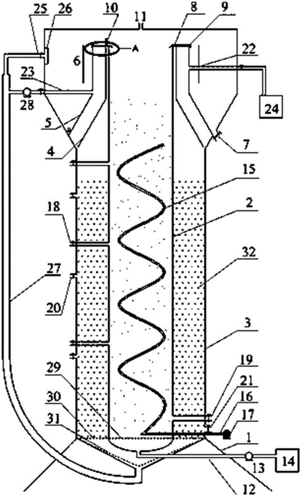
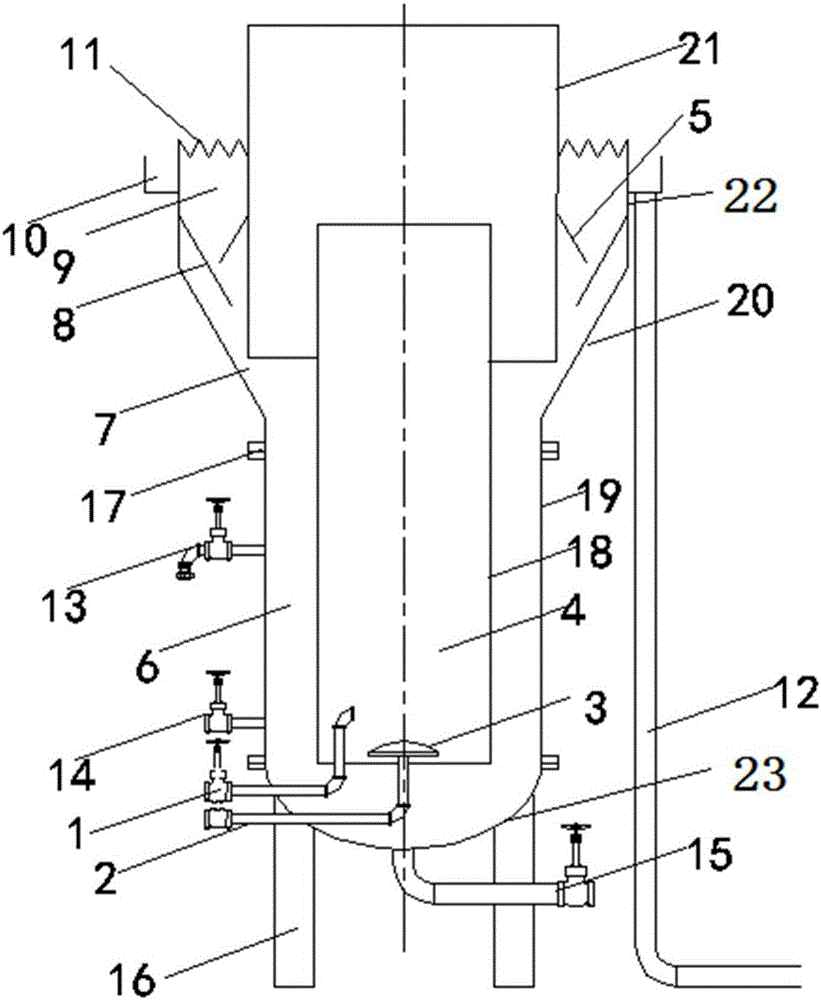
[0027] The invention provides an integrated autotrophic synchronous biological denitrification granulation device, such as figure 2 As shown, including a bracket 16, the bracket 16 is provided with an arc-shaped bottom surface 23, the bottom surface 23 is provided with an outer cylinder 19, the inside of the outer cylinder 19 is provided with an inner cylinder 18, the inner cylinder 18 is a reaction zone 4, and the outer cylinder 19 Inside and outside the inner cylinder 18 is the recirculation zone 6; the water inlet pipe 1 and the air inlet pipe 2 both pass through the bottom of the bottom surface 23 and extend into the inner cylinder 18, and the end of the air inlet pipe 2 in the inner cylinder 18 is c...


PUM

PropertyMeasurementUnit
widthaaaaaaaaaa

Abstract

The invention discloses an integrated autotrophic synchronous biological denitrification granulation device which comprises an outer barrel arranged on a support.An inner barrel is arranged inside the outer barrel, both a water incoming pipe and an air incoming pipe penetrate the undersurface to extend into the inner barrel, the end of the air incoming pipe in the inner barrel is connected with an aeration head, the top of the outer barrel is connected with a sludge backflow slope, a sedimentation barrel is connected above the sludge backflow slope, an overflow weir is arranged at the upper edge of the sedimentation barrel, a water collection tank is arranged outside the sedimentation barrel, an isolation barrel is arranged at the top of the inner barrel in a sleeved manner, a sludge backflow gap is formed between the isolation barrel and the sludge backflow slope, the top of the isolation barrel is higher than the sedimentation barrel, a second gas-water separation annular baffle is connected on the inner wall of the sedimentation barrel, and a first gas-water separation annular baffle is arranged at a position above the second gas-water separation annular baffle and on the outer wall of the isolation barrel.A circulating device does not need to be added externally, so that energy conservation is realized; granular sludge can be cultured under action of self-circulation, and setting performance is good.

Description

technical field [0001] The invention belongs to the technical field of denitrification of wastewater, and in particular relates to an integrated autotrophic synchronous biological denitrification granulation device. Background technique [0002] The most widely used waste water nitrogen removal technology is wastewater biological nitrogen removal technology. The traditional wastewater biological nitrogen removal technology is nitrification-denitrification process, that is, ammonia nitrogen is oxidized to nitrate nitrogen (NH 4 + →NO 3 - ) and then in the denitrification section the nitrate nitrogen is converted into nitrogen emission (NO 3 - →N 2 ). The traditional process requires a large amount of oxygen consumption and energy consumption, and additional carbon sources, and the output of residual sludge is high and the efficiency is low. In order to solve these problems, the researchers developed a short-cut nitrification-ANAMMOX denitrification process, which uses ...

Claims


Application Information

Patent Timeline
Patent Type & Authority Applications(China)
IPC IPC(8): C02F3/30
CPCC02F3/307C02F2203/006C02F2301/04
Inventor 王兰王智勇邓良伟张云红郑丹
Owner BIOGAS SCI RES INST MIN OF AGRI
Why Eureka
Try Eureka